FPC solder joints may show good continuity and acceptable soldering appearance initially, yet fracture after vibration, plugging/unplugging or thermal cycling. The common root cause is often poor soldering quality. Instead, continuous mechanical stress generated by FPC bending and harness displacement concentrates at the root of solder joints. For such failures, solder joint protection should be upgraded from simple coating with adhesive to forming a flexible stress transition zone.
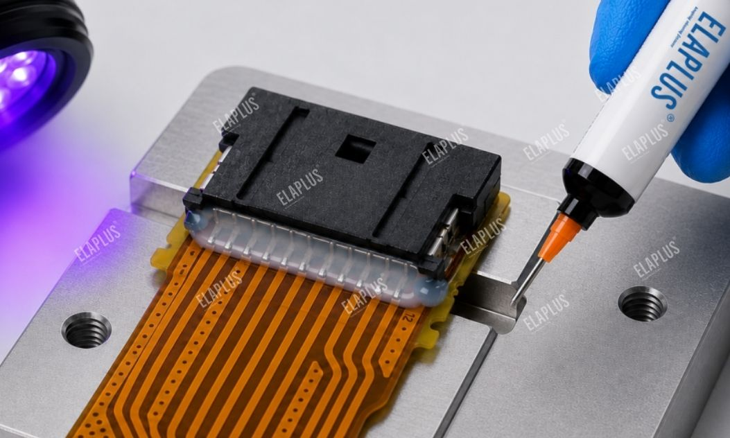
UV Adhesive for FPC Reinforcement
FPC, flexible flat cables and fine wire harnesses are inherently flexible, while solder joints form rigid connections.
The boundary between flexible and rigid materials is naturally prone to stress concentration. This explains why many products pass factory tests but develop intermittent contact failures after prolonged vibration.
1. Why Solder Joints Can Crack Even Without Cold Solder Joints
Solder is designed to establish reliable electrical interconnection, rather than to withstand repeated harness bending as a structural component over long service life. When FPC is subjected to:
- Vibration
- Tension
- Mating and unmating
- Bending
- Thermal expansion and contraction
External loads propagate along the flexible circuit to the rigid soldering area. Without stress buffering, the bending neutral axis tends to stay at the solder edge or the root of FPC copper foil. Consequential failures include:
- Copper foil fatigue fracture
- Solder joint cracking
- Intermittent circuit open
A fracture appearing at the solder joint does not necessarily mean the soldering process is defective.
2. How to Distinguish Soldering Defects from Mechanical Fatigue
Judge by failure occurrence conditions:
| Failure Phenomenon | Primary Judgment | Recommended Inspection Items |
|---|---|---|
| No conductivity right after soldering | Soldering anomaly | Wetting, solder material, soldering temperature |
| Normal at rest, open circuit after bending | Root stress concentration | FPC bending position |
| Intermittent open circuit after vibration test | Fatigue failure | Solder joint / FPC interface |
| Abnormality after several mating cycles | Tension transfer | Harness fixation |
| Resistance drift after thermal cycling | Thermo-mechanical stress | Copper foil, solder joints |
| Failure immediately after adhesive curing | Curing-induced stress | Adhesive dosage, hardness |
| Repeated fracture at the same location | Structural defect | Stress concentration point |
The most valuable clue: whether failure can only be reproduced with motion. If performance remains stable statically but fails under bending, pulling or vibration, mechanical stress shall be prioritized for troubleshooting.
3. Why FPC Often Breaks Right at the Adhesive Edge
Many reinforcement designs use adhesive but only cover a tiny area over the solder joint. The solder joint becomes stronger, yet a new rigid-flex boundary is created at the adhesive termination. A steep adhesive edge concentrates all FPC bending along that single line, forming a new stress concentration boundary.
FPC reinforcement is not simply about using harder or thicker adhesive. The real target is to gradually transfer stress from rigid solder joints to flexible FPC.
4. Selection Between Spread-Type and Build-Up Reinforcement
Selection depends on the area to be protected:
| Structural Requirement | Preferred Adhesive Rheology | Core Purpose |
|---|---|---|
| Thin-layer protection over solder surface | Moderate flowability | Complete coverage |
| Reinforcement at FPC root | Controlled build-up | Build buffer zone |
| Around narrow pads | Precision dispensing | Prevent adhesive wicking |
| Harness exit | Flexible build-up | Stress relief |
| Large-area film protection | Flowable grade | Uniform coverage |
| Vertical / side surfaces | Thixotropic grade | Anti-sagging |
There is no absolute good or bad for material flowability. It shall flow where needed and stay where restricted.
5. Why UV Adhesives Are Suitable for FPC Solder Joint Reinforcement
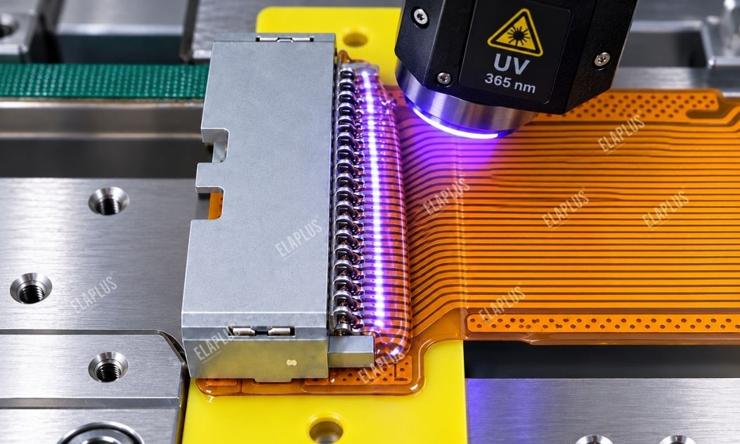
A major advantage of UV-curable systems is fast positioning and curing right after dispensing, which fits automated mass production well.
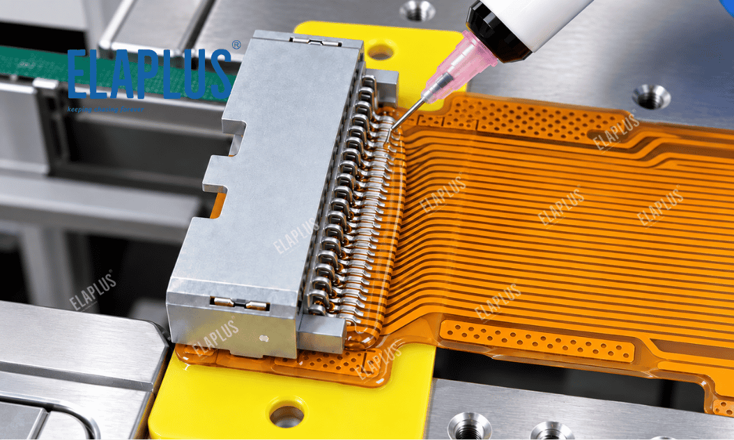
For example, UV 1017 is a one-component transparent UV acrylic electronic adhesive, viscosity ~7400 cps, Shore D 50, with decent elongation. It is used for harness fixation and solder joint protection of electronic components.
If obvious build-up height is required for the structure, thixotropic grades are recommended. UV 1018T is a one-component thixotropic UV adhesive, viscosity ~23000 cps, cured Shore A 60. It can form defined build-up profiles for harness fixation, solder joint protection and gap sealing.
The key difference is not which grade has superior parameters, but whether the zone needs flow-out coverage or a 3D stress buffer structure.
6. Why Reinforcement Adhesive Should Not Be Selected Solely for High Hardness
Hard adhesive can firmly lock solder joints in place. Nevertheless, the FPC itself will still move under external loads. Mechanical stress does not disappear; it may shift to:
- Adhesive edge
- Copper foil
- FPC substrate
Reinforcement materials need balanced properties:
- Adhesion
- Flexibility
- Elongation
- Curing shrinkage
- Thermal cycling resistance
That is why solder reinforcement materials cannot be equated with ordinary high-strength structural adhesives.
7. Why Dispensed Adhesive Profile Affects Service Life
An ideal reinforced zone shall avoid steep steps. The adhesive shall form a gradual transition from the solder area toward the FPC: high stiffness → medium stiffness → low stiffness, instead of an abrupt termination. When FPC bends, curvature change will not concentrate along one sharp line. For devices under long-term vibration, geometric profile design often matters more than simply increasing adhesive volume.
8. Typical Applications Requiring Solder Joint Reinforcement
- Automotive electronic sensors: subject to persistent vibration and temperature cycling
- PV inverters and micro-inverters: internal solder joints endure thermal cycling and outdoor exposure; ELAPLUS inverter solutions adopt MA 1012 UV for solder joint protection
- Robots and motion control equipment: repetitive harness movement
- Small camera modules, display modules and sensor FPC: limited space with tight minimum bending radius
9. Mass Production Inspection: Do Not Only Check Curing Completion
Four inspection items are recommended:
- Adhesive placement: whether it crosses the boundary between solder joint and FPC
- Adhesive profile: smooth stress transition instead of sharp edges
- No-adhesive zones: check contamination on connectors, contact terminals, camera and optical surfaces
- Curing status: sufficient UV energy delivered to target areas. For shadowed complex structures, verify light access.
10. How to Validate Reinforcement Effectiveness
Tensile testing alone is insufficient. Prepare paired samples: unreinforced and reinforced. Run tests including:
- Repeated FPC bending
- Harness pull test
- Vibration test
- Thermal cycling
Monitor:
- Continuity status
- Resistance variation
- Crack initiation location
If fracture merely transfers from solder joint to adhesive edge after reinforcement, stress has not been properly relieved. Adjust:
- Adhesive profile
- Dispensing volume
- Coverage length
- Edge transition geometry
11. Solder Reinforcement Essentially Optimizes Stress Paths
Many engineers only focus on failure locations: Solder crack → replace solder alloy FPC crack → use thicker FPC
If external displacement keeps transferring stress to the same spot, failure will recur even after material replacement. A better approach is to map load sources and track stress propagation routes. ELAPLUS FPC and solder protection solutions focus on building stress buffers via combined material and structural design, rather than blindly boosting adhesive strength.
FAQ
Q: Is harder adhesive always better for FPC solder reinforcement?
A: No. Excessively high hardness may shift stress to adhesive edges or FPC copper foil. Both fixation and flexible buffering must be balanced.
Q: Why does fracture still occur at adhesive edge after dispensing?
A: A new stress concentration point forms at the adhesive termination. Check coverage length and transition profile.
Q: What is the difference between UV 1017 and UV 1018T?
A: UV 1017 suits solder protection requiring moderate flow and coverage; UV 1018T features thixotropy and build-up capability for 3D structural reinforcement.
Q: What tests are required after solder reinforcement?
A: At minimum, run comparative bending, vibration, pull and thermal cycling tests, and check whether crack positions shift.
Previous post: Why Does Insulation Degrade Under High Humidity Even After Conformal Coating on BMS PCBs? Film Protection and Potting Are Not Interchangeable
Next post: Pin Sealing for Automotive Connectors: Why Surface Sealing Alone May Still Allow Water Ingress? Reliable Sealing Must Be Achieved at the Terminal Root