When specifying material between the integrated heat spreader (IHS) of GPUs and CPUs in AI servers and cold plates or heat sinks, thermal conductivity alone shall not be the primary selection criterion. ELAPLUS SIGR 2250 thermal grease may be considered for flat mating surfaces requiring a thin interface under consistent screw‑driven clamping pressure; its published thermal conductivity is 5.1 W/m·K, with microprocessors listed among typical applications. For assemblies prone to warpage, variable gaps, or where automated dispensing and shot‑volume control are preferred, ELAPLUS TCMP 3365 one‑component post‑cure thermal gel can be evaluated against the actual mechanical design. Its published thermal conductivity reaches 6.2 W/m·K with a minimum controllable bond‑line thickness (BLT) of 100 μm. Final material selection must be validated through stack dimensions, assembly pressure and system temperature‑rise testing.
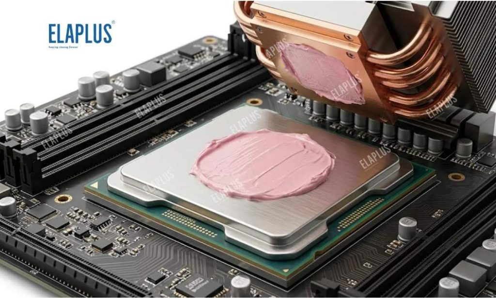
Identify the Target Thermal Interface First
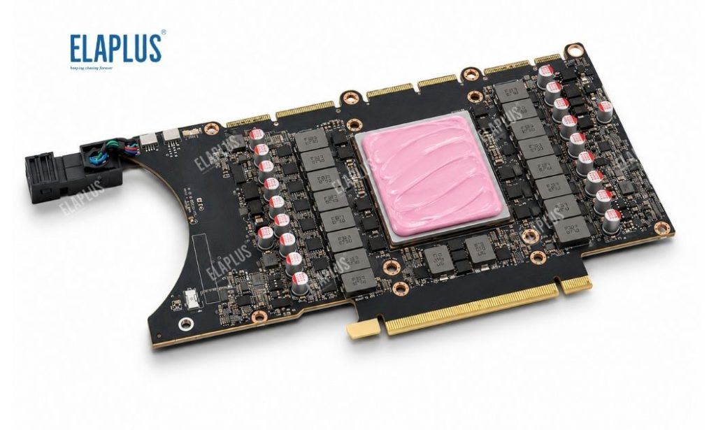
Inside an AI server, the typical thermal path runs from the package IHS, through the thermal interface material, to a vapour chamber or cold plate, then onward to the heat sink, air duct or liquid cooling loop. This article addresses only the interface between the chip IHS and its adjacent cooling component; the TIM itself is not a substitute for the heat sink. GPUs, CPUs, switch chips and power modules differ in heat flux, clamping scheme and serviceability, even within the same server platform, and may therefore require distinct thermal solutions. Four sets of baseline data should be collected before thermal modelling: contact area and flatness, minimum and maximum assembly gap, clamping force plus tolerance, and intended rework strategy.
Preliminary Screening: Grease vs Thermal Gel
| Construction / Operating Condition | Key Evaluation Focus | Candidate Grade | Validation Boundaries |
|---|---|---|---|
| Flat IHS‑to‑cold‑plate interface, thin bond line, stable screw clamping | Fill micro‑voids and control excessive squeeze‑out | SIGR 2250 thermal grease | Shot volume, coverage after compression, interface integrity after thermal cycling |
| Variable gaps, large component height tolerance, or automated dispensing required | Compliance with deformation and gap variation, process repeatability | TCMP 3365 one‑component post‑cure thermal gel | Actual BLT above 100 μm, cure window and rework workflow |
| Frequent disassembly planned | Residue removal, cleaning and re‑coating performance | Selected per maintenance procedure | Reproducible temperature rise after multiple reassemblies |
Note: SIGR 2250 qualifies as a candidate thin‑interface thermal grease; TCMP 3365 qualifies for dispensing‑friendly designs with assembly tolerance. Listing as a candidate does not constitute a performance guarantee for any specific server stack.
Determining the Coating Volume
For thermal grease, target volume shall be derived backwards from the intended bond‑line thickness and effective coverage area. Record coated footprint, compression load and transfer pattern on process coupons, then correlate these observations with thermal readings. If heavy, consistent squeeze‑out occurs at edges, first adjust dispense pattern, shot size and tightening sequence instead of simply upgrading to a higher‑conductivity grade.
For thermal gel, lock dispense path, shot weight, open time and cure schedule into controlled process parameters. Variation across shifts in application behaviour can otherwise become a major source of thermal resistance drift.
Ensuring Comparable Temperature‑Rise Tests
When benchmarking materials, fix chip power dissipation, cold plate / heat sink hardware, airflow or liquid flow rate, ambient temperature, fastener torque and thermocouple locations. Run steady‑state loading first and log stable temperatures and differential readings. If scatter appears, disassemble samples to inspect coverage and material migration. Judgement shall not rely on a single peak reading; results obtained with different heat sinks or clamping loads cannot be directly compared.
Mass Production and Long‑Term Qualification
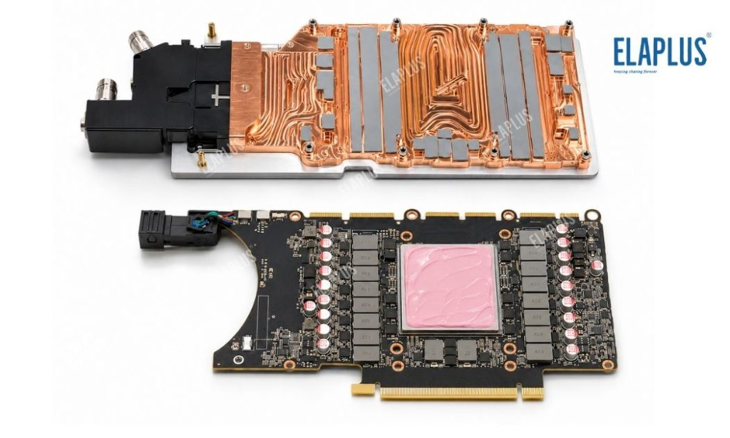
Incoming inspection, storage and conditioning, dispensing or coating equipment, fixture alignment, tightening sequence, cure profile and sampling plans should be consolidated within one control plan.
For TCMP 3365, confirm that the minimum achieved bond line on prototypes satisfies the mechanical design before implementing gravimetric dispense control or visual inspection criteria. For SIGR 2250, define the coated region, allowable shot size and acceptable post‑compression edge condition. Prototype validation shall include thermal cycling, power cycling or extended soak testing, with retests to capture temperature drift, squeeze‑out, coverage degradation and disassembly behaviour.
FAQ
Q1: Can SIGR 2250 and TCMP 3365 be selected solely by thermal conductivity?
A: No. They differ in physical form and application logic. SIGR 2250 targets thin, stably clamped interfaces, while TCMP 3365 requires separate qualification of actual BLT, dispensing process and cure window.
Q2: Does TCMP 3365’s rated minimum BLT of 100 μm mean all designs must adopt 100 μm?
A: No. This is the published lower limit for controlled bond lines. The final design thickness shall be determined by stack tolerance, coverage requirement and thermal testing.
Q3: Can thermal qualification be skipped?
A: Not recommended. Material selection must close the loop across mechanical design, manufacturing process and system‑level thermal validation.