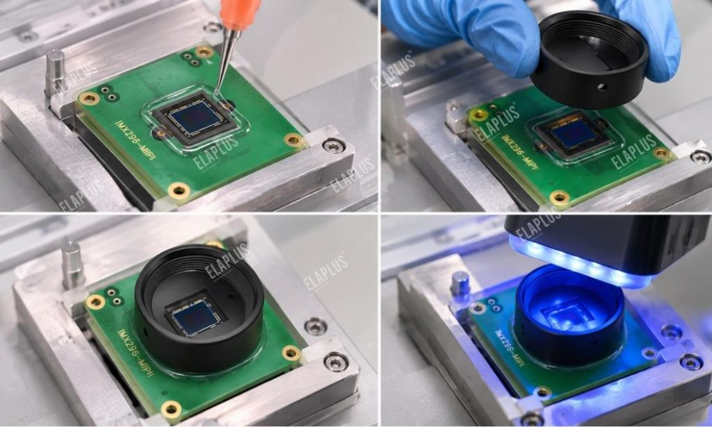
ELAPLUS UV 1018, a one‑component UV‑curable adhesive, may be evaluated for local solder joint fixation on camera modules. It is suitable for dispensing at locations accessible to curing light, where adhesive can be kept away from restricted zones such as lenses and connectors. If brackets or flexible cables block light entirely, adjust the light path or assembly sequence first, then verify through mass‑production hardware whether full cure is achieved at the bottom of the dot and whether module functionality remains intact.
| Selection Consideration | Validation during Prototyping |
|---|---|
| Can light reach the entire adhesive dot? | Check for obstruction by brackets and flex cables following the actual assembly sequence; focus on cure at the dot base |
| Is the dispensed volume appropriate? | Confirm solder joint coverage, adhesive boundary and closing clearance; check for overflow into restricted zones |
| Will dispensing impair module performance? | Compare connection stability and imaging before and after dispensing; retest following environmental qualification |
Permissible Dispensing Zones
Mark designated solder joint reinforcement points on assembly drawings, together with no‑adhesive areas including lenses, photosensitive surfaces, connector contact regions and moving components. Verify access for dispensing needles and light sources against the physical assembly sequence. ELAPLUS lists UV 1018 as a candidate one‑component UV adhesive for solder joint fixation in camera modules for eligible designs.
Post‑Cure Checks beyond Surface Skinning
Inspect the base of adhesive dots, edges obscured by components and thicker cross‑sections. Record irradiation distance, angle, shot volume and actual equipment parameters during prototyping. Set up tests in accordance with the product datasheet, and confirm cure level against supplier guidelines and internal process specifications. If permanent obstruction remains after assembly, evaluate whether the assembly sequence or light path can be revised; otherwise, reassess alternative curing chemistries for that construction.
Module Acceptance Criteria
Compare paired samples from the same batch before dispensing, after dispensing and after environmental cycling. Inspect for adhesive overflow into restricted areas, loose reinforcement points and stable electrical connectivity. For placements adjacent to optical paths, check for newly introduced visible artefacts under identical imaging conditions.
Root‑Cause Assessment for Solder Joint Reinforcement
Identify whether failures arise during assembly, handling or end‑use. If flex bending transmits load into solder joints, review flex routing, bend allowance and supporting features alongside the joint itself. If poor soldering is the primary defect, resolve it via the welding process first. Define the loading scenario the adhesive is intended to mitigate before setting dot coverage and acceptance criteria, so excess adhesive does not mask inspection points or hinder rework.
Optimising Shot Volume and Irradiation Sequence
Produce initial coupons using production‑representative pads, flex cables and brackets. Confirm needle access to target locations, and check whether uncured adhesive creeps toward restricted zones before exposure. Log the delay between dispense completion and UV trigger, and evaluate coverage across different allowable shot sizes. For oversized dots, pay special attention to thick adhesive build‑up at component edges and mechanical interference after lid closure.
Compare light accessibility before and after bracket installation. Use drawings and physical samples jointly to identify shadowing from brackets, flexes or neighbouring components. If irradiation can be completed before bracket fitting, still verify whether subsequent assembly compresses the cured dot. For dual‑side exposure schemes, confirm full coverage from both directions on hardware, and document lamp positioning and fixture layout within process instructions.
Distinguishing Surface Cure from Subsurface Cure
Retain destructible process coupons from each batch to examine cross‑sections or dot bases at representative thicknesses and partially shadowed locations, using approved evaluation methods. Separate records for directly illuminated zones and suspected shadow regions; surface tack alone is not sufficient to judge full cure. Do not reuse process parameters from other suffix variants of UV 1018; follow the datasheet for the exact grade and installed light source.
Transferring Lab Results into Mass‑Production Inspection Items
Capture results under three categories: appearance, functionality and reliability. Visual inspection covers dot placement, coverage and overflow. Functional inspection verifies stable connectivity and compares imaging under fixed illumination, focal length and test‑chart conditions before and after dispensing. Reliability testing follows the module’s specification; after cycling, examine adhesive dots and flexes, and record fracture locations: adhesive bulk, interfacial boundary or solder joint. If repeated anomalies occur at the same location, trace fixture orientation, dispense delay, lamp output and bracket assembly sequence to check reproducibility.
FAQ
Q: Can longer irradiation resolve under‑cure in shadow areas?
A: First confirm whether light can reach the adhesive. For fully blocked locations, qualify alternative light paths, revised assembly sequences or alternative curing systems.
Q: Can UV 1018 be used directly for lens bonding?
A: Lens bonding carries different acceptance requirements from solder joint reinforcement. Separate material selection is required based on substrate, assembly tolerance and optical performance.
When requesting prototypes, provide module photographs, drawings of reinforcement points and restricted zones, assembly sequence and existing UV light source conditions.