Even fully potted high-voltage modules may suffer creepage, partial discharge or even dielectric breakdown. Adhesive coverage alone does not guarantee a continuous, defect-free insulation path inside the assembly. Air gaps at pin roots, electric field concentration at sharp edges, interfacial delamination, residual contamination and insufficient effective insulation distance after potting can all initiate high-voltage failures.
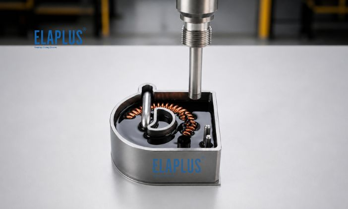
For 800 V and higher voltage platforms, potting reliability shall not be judged merely by whether the cavity is fully filled. Instead, evaluation should focus on the electric field distribution and insulation path formed between high-voltage potential points.
1. Distinguish Breakdown, Creepage and Partial Discharge
First: Dielectric breakdown means the insulation medium loses its insulating capability. Under strong electric fields, a conductive channel forms within the originally insulating region, which may directly cause a short circuit between high voltage and low voltage.
Second: Creepage refers to conductive paths developing along insulation surfaces. Moisture, contamination and ionic residues raise the creepage risk. Even if high-voltage terminals are covered by adhesive, unstable surface or interfacial conditions do not eliminate creepage hazards.
Third: Partial discharge takes place locally within the insulation system. It may not trigger immediate complete breakdown. Nevertheless, repeated discharge over time progressively erodes local insulation and eventually leads to severe electrical failure.
In short: No short circuit does not mean the insulation system is free from degradation.
2. Why Tiny Internal Voids Matter Greatly for High-Voltage Potting
For high-voltage potting, the primary hazard is not limited to large bubbles visible to the naked eye. More risky defects often include:
- Micro voids at pin roots
- Air layers along copper busbar edges
- Incomplete filling beneath components
- Local delamination between adhesive and housing
These locations form a discontinuous structure: solid insulation – air – solid insulation. Electric field redistribution occurs accordingly. The real goal of high-voltage potting is continuous insulation, rather than a visually full appearance.
3. Why Pin Tips and Sharp Corners on Busbars Are High-Risk Zones
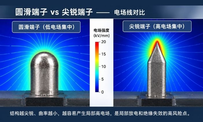
Electric field is not uniformly distributed across all features. Sharp geometries with small radii are prone to local electric field concentration. Typical vulnerable locations:
- Pin tips
- Raised solder joints
- Sharp edges of copper busbars
- Metallic burrs
- Terminal roots
- Closely spaced high-voltage and low-voltage conductors
Even if most parts of the module are well designed, a combination of sharp features + air voids + contamination near a high-voltage terminal creates a critical high-risk zone.
4. Failure Symptoms and Priority Inspection Items
| Failure Symptom | Priority Inspection | Key Locations |
|---|---|---|
| Intermittent hipot test failure | Micro voids / structural variation | Pins, busbar edges |
| Insulation degradation under high humidity | Interfaces / contamination | Housing, terminal roots |
| Recurring failure at fixed positions | Electric field concentration | Sharp corners, metal burrs |
| Failure emerges after thermal cycling | Interfacial delamination | Adhesive-metal, adhesive-plastic interfaces |
| Wide scatter across batches | Potting process | Dispensing, degassing, curing |
| Visible discharge marks on surfaces | Creepage path | Surfaces between high and low voltage |
| Passes initially, fails after ageing | Long-term insulation degradation | Interfaces and material condition |
Recurring failure at the same spot usually indicates structural issues; random failures point primarily to process variation. This troubleshooting logic applies equally to high-voltage coils, BMS sampling circuits, OBC and power electronic modules.
5. Why High Dielectric Strength of the Adhesive Alone Is Not Sufficient
Dielectric strength characterises a bulk material’s resistance to electrical breakdown under specified test conditions. However, a real module is not a homogeneous block of adhesive. It incorporates:
- Metals
- Plastics
- PCB substrates
- Solder joints
- Pins
- Interfaces
- Air inclusions
The system operates as a composite insulation assembly consisting of multiple materials and interfaces.
For example, SIGEL 1875 is a 1:1 addition-curing dielectric silicone gel. It has a mixed viscosity of approximately 750 cps and dielectric strength up to 25 kV/mm, featuring soft texture, self-healing performance and high-voltage insulation protection.
Even with high bulk dielectric strength, engineering design must still avoid:
- Air voids
- Contamination
- Sharp-point electric field stress
- Interfacial separation
Therefore, adequate dielectric strength is a necessary condition, yet not the full guarantee of high-voltage system reliability.
6. Why Low Viscosity Matters for Complex High-Voltage Structures
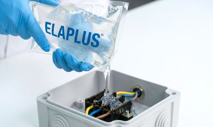
When high-voltage terminals are densely arranged, the potting material needs to penetrate into narrow spaces such as:
- Pin roots
- Clearances between terminals
- Gaps between PCB and housing
- Areas around solder joints
- Edges of copper busbars
Insufficient flowability may result in a visually covered top layer while hidden voids remain underneath. Low-viscosity materials facilitate filling of intricate gaps, but low viscosity is not universally better. Additional factors require control:
- Adhesive wicking
- Leakage
- No-adhesive zones
- Flow behaviour before cure
Flowability must be matched with structural design.
7. Why Insulation Failures Often Show Up After Thermal Cycling
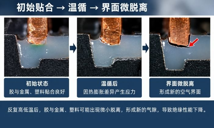
Freshly potted adhesive can form good contact with copper, aluminium, PCB and plastics initially. These materials differ in thermal expansion behaviour. Repeated heating and cooling subjects interfaces to tension, compression and shear stress. Accumulated micro-delamination creates new air interfaces.
A single room-temperature hipot test is insufficient for high-voltage modules. A more valuable validation sequence: initial insulation test → thermal cycling → re-test insulation → interface dissection. This reveals potential long-term failure risks.
8. Can Potting Directly Reduce Required Creepage Distance?
Potting shall not be regarded as permission to arbitrarily reduce the original electrical clearance. High-voltage design takes into account:
- Operating voltage
- Transient voltage
- Contamination level
- Insulation performance of materials
- Structural geometry
- Interfacial stability
- Applicable safety standards
Potting improves environmental isolation and insulation protection, but final clearance dimensions must be verified against the system-level electrical safety requirements.
In particular, simple calculation such as “the adhesive has 25 kV/mm dielectric strength, so 1 mm thickness is sufficient” is invalid for structural design. These belong to different evaluation tiers.
9. Key Zones to Focus on for 800 V High-Voltage Modules
High-voltage assemblies commonly contain high-voltage connection terminals, busbars, sampling circuits and power electronic units exposed continuously to high voltage, humidity and vibration. Recommended inspection priorities:
- Pin roots: Verify complete bottom filling
- Sharp edges of busbars: Check chamfering, burrs and full adhesive coverage
- Boundary between high voltage and low voltage: Confirm valid insulation paths
- Housing edges: Prevent potential creepage routes along interfaces
- Raised solder joints: Watch for local electric field concentration and trapped air
10. Add Cross-Section Validation for High-Voltage Potting
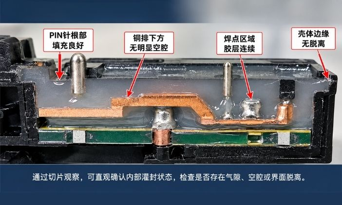
Many projects only carry out tests for appearance, hardness, hipot resistance and insulation resistance. For complex structures, cross-section inspection is strongly recommended. Check mainly for:
- Air pockets under pins
- Voids beneath busbars
- Complete penetration of adhesive into narrow gaps
- Interfacial delamination
If available, supplementary inspection by X-ray, CT scanning or specimen sectioning helps assess internal potting quality. The most dangerous defects in high-voltage potting are usually invisible from the outside.
11. Material Selection Based on Insulation System Rather Than Single Parameter
Material selection for high-voltage electronic protection evaluates multiple requirements simultaneously:
| Requirement | Key Indicators to Evaluate |
|---|---|
| High-voltage insulation | Dielectric properties |
| Micro-gap filling | Flowability |
| Thermal cycling reliability | Flexibility / interfacial stability |
| High-humidity environment | Moisture resistance |
| Vibration and shock | Stress buffering |
| Dense terminals | Degassing and wetting performance |
| Long-term operation | Ageing stability |
Flexible dielectric gels such as SIGEL 1875 are optimised for low-stress, high-voltage insulation and moisture protection. Applications requiring strong mechanical fixation need a different material system.
ELAPLUS’s selection philosophy is not simply to source the adhesive with the highest dielectric strength. Instead, identify failure modes first and then define the functional role the adhesive needs to perform.
FAQ
Q: Is creepage still a concern after a high-voltage module is fully filled with adhesive?
A: Yes. Potting enhances environmental isolation and insulation protection, but high/low voltage layout, interfaces, contamination, electric field concentration and long-term ageing still need consideration.
Q: Does higher dielectric strength of adhesive guarantee a safer high-voltage module?
A: This conclusion cannot be drawn directly. Bulk dielectric property is only one factor. Actual reliability depends on voids, structure, electric field distribution and interface condition.
Q: Why do high-voltage pin roots frequently fail?
A: These areas are prone to air entrapment and feature sharp metal edges within narrow gaps, requiring attention from both electric field design and potting process.
Q: Why does a module pass hipot initially yet fail after thermal cycling?
A: Focus inspection on delamination between adhesive and metal/plastic substrates and new micro voids generated by thermal cycling.
Previous post: Why Rain & Light Sensor Sensitivity Drops After Dispensing Adhesive: Transparency Is Not Enough — Bubbles, Adhesive Thickness and Optical Bonding Are the Key
Next post: Does Foam Material Have to Replace All Potting Adhesives for Battery Module Weight Reduction? Differentiate Filling, Thermal and Structural Functions First