For encapsulation of internal circuits in automotive Hall position sensors, insulation potting adhesives with appropriate flowability, interfacial adhesion and medium resistance shall be selected according to the actual structure of engineering plastic housings such as PA66, metal terminals and PCBs. Special priority shall be given to verifying sealing continuity at the terminal feed-through positions. If the sensor is exposed to oil for long-term operation or subjected to thermal cycling, room-temperature waterproofing and initial adhesion tests alone cannot prove encapsulation reliability.
Hall position sensors detect magnetic field changes via Hall elements, and work with magnets and signal processing circuits to measure position, angle or motion status. Widely used in automotive actuators, industrial motors and other position feedback systems, a typical sensor assembly consists of a Hall chip, PCB, metal connecting terminals and an engineering plastic housing.
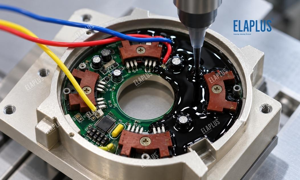
The main functions of encapsulation adhesive are to protect internal circuits, fix partial structures and mitigate ingress of external media. Nevertheless, sensors often feature complex zones such as terminal roots, housing corners and PCB peripheries. Continuous protective coverage in these critical areas matters more than simply coating the entire cavity surface.
Why Special Attention Is Required for Terminal Feed-Through Zones in Hall Sensor Encapsulation
Material and structural discrepancies exist between metal terminals and plastic housings. Even if terminals are fixed by insert moulding or other processes, the surrounding interfacial area requires careful evaluation.
When the sensor undergoes temperature fluctuation, metal terminals and engineering plastics exhibit different thermal expansion behaviours, subjecting the adjacent interface to repeated deformation. Discontinuous adhesive coverage or insufficient bonding to the substrate in this zone compromises long-term sealing performance.
Therefore, sealing design at terminal roots cannot rely solely on the nominal temperature range of the potting material. Validation shall combine terminal geometry, housing structure and actual thermal cycling conditions.
For sensors with multiple metal terminals, insulation protection between adjacent terminals shall meet design specifications, and adhesive overflow onto undesired electrical contact areas must be avoided.
What to Inspect First for Hall Sensor Encapsulation Failures
It is recommended to distinguish electrical malfunctions, housing leakage and interfacial degradation of encapsulation. Even if these symptoms occur simultaneously, they may stem from different root causes.
| Symptom | Priority Inspection Area | Recommended Verification Method |
|---|---|---|
| Medium ingress near terminals | Interface between metal terminal and plastic housing | Leak path mapping and cross-section inspection |
| Recurring defects at fixed corners | Housing structure and local adhesive thickness | Inspect mould design and dispensing route |
| Random sealing defects across samples | Dispensing, mixing and curing process | Compare production parameters |
| Leakage after thermal cycling | Dissimilar-material interface and adhesive deformation | Sealing test before and after cycling |
| Abnormal sensor output with intact sealing | Hall element, circuit or magnetic circuit | Electrical function and magnetic field testing |
| Performance degradation after medium exposure | Material-medium compatibility | Soaking, cycling and function retest |
If failures concentrate on the same terminal or housing location, examine structural and interfacial design first. Random defects point to dispensing volume, mixing quality and curing consistency.
In particular, Hall signal abnormalities shall not be directly attributed to encapsulation adhesive. Sensor output is also affected by magnet placement, power supply, circuit design and ambient magnetic fields, which must be ruled out via independent functional tests.
Why PA66 and Glass-Filled Plastics Cannot Be Selected Merely by Material Grade
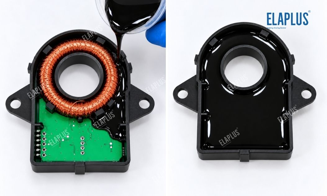
PA66 is an engineering plastic, and sensor housings may adopt glass-fibre-reinforced grades or other modified formulations. Variations in compound recipe, surface condition and injection moulding process affect adhesive bonding to the housing.
For PA66 + GF housings, glass fibre content, exposed surface fibres and residual mould release agent alter practical adhesion. Hence, test results obtained on standard PA66 coupons cannot be extrapolated to all glass-reinforced variants.
Plastic housings may also contain weld lines, corners and terminal inserts. The encapsulation adhesive shall form coverage as specified at these locations, yet it cannot mask inherent moulding defects of the housing.
Material validation shall use mass-production housings and terminals, rather than generic plastic test coupons only.
Why Oil Resistance Must Be Validated against the Actual Working Medium
Automotive sensors may come into contact with lubricating oil, hydraulic fluid or other working media, which differ greatly in chemical composition, additive packages and operating temperature. Stable performance in one fluid does not guarantee long-term compatibility with all oil types.
For encapsulation structures exposed to oil, monitor mass change, dimensional shift, mechanical property retention and interfacial integrity of the adhesive after immersion. Compatibility of metal terminals, housing materials and other seals with the medium shall also be confirmed.
Where oil exposure and thermal cycling coexist, combined environmental tests under near-real operating conditions are preferred over static room-temperature soaking.
A clear distinction shall be made between bulk material oil resistance and assembly-level oil resistance. Even if the adhesive itself shows negligible change, the interface between terminals and housing remains a critical inspection point.
Selection Guidance for Epoxy Potting Adhesive, Silicone and Local Sealants
Different material systems differ in mechanical properties and process suitability. For Hall position sensors, define whether the encapsulated zone undertakes structural fixation before choosing full cavity filling or local sealing.
| Encapsulation Requirement | Preferred Material Category | Key Validation Items |
|---|---|---|
| Internal circuit protection and structural anchoring | Suitable epoxy potting adhesive | Substrate adhesion, curing behaviour and insulation |
| High flexibility requirement | Suitable silicone material | Deformation tolerance, sealing and medium compatibility |
| Local sealing at terminal roots | Sealant formulated for spot application | Interfacial continuity and leak path check |
| Filling of deep or complex cavities | Potting system with matched flowability | Actual filling performance and curing state |
| Long-term exposure to specified oil | Material validated in target medium | Immersion, cycling and function retest |
High strength of epoxy does not make it suitable for all sensors; similarly, the softness of silicone does not automatically equate to superior long-term sealing. Applicability is determined by structure, medium and process conditions.
Is EP 2023 Suitable for Internal Encapsulation of Hall Position Sensors?
Within ELAPLUS automotive sensor solutions, EP 2023 is listed as a candidate epoxy material for internal circuit protection and waterproof sealing of Hall-effect position sensors, featuring substrate adhesion, impact resistance, oil resistance and acid/alkali resistance.
EP 2023 can be shortlisted for Hall position sensors with engineering plastic housings, metal terminals and internal PCBs. Note that listing for such applications does not guarantee identical bonding performance on every PA66 or glass-filled plastic housing.
During material selection, confirm that the material can reach terminal roots and target circuit zones and form continuous encapsulation under specified curing profiles. For deep or narrow cavities, verify compatibility of dispensing equipment, dispense sequence and material flowability.
If the sensor operates in sustained contact with specific oil, testing shall be carried out using the actual fluid before mass production release, instead of relying on general oil-resistance descriptions.
How Dispensing Sequence Affects Final Quality
In complex sensor cavities, PCB, terminals, support ribs and housing geometry restrict the flow path of adhesive. Improper dispensing placement may lead to surface coverage while failing to fully penetrate critical terminal zones.
Process design shall define the dispensing start point, nozzle position, shot size and filling sequence according to the real cavity layout. For multi-compartment structures, confirm continuous flow paths between separate zones.
When adhesive covers the PCB, identify connectors, test pads and functional areas that must remain uncontaminated. For assemblies intended for later inspection or maintenance, check whether the encapsulation method aligns with service requirements.
For mass production, control glue volume, dispense trajectory, curing conditions and critical-zone inspection, rather than judging encapsulation quality solely by visual appearance.
How to Validate Compatibility of EP 2023 with the Actual Hall Sensor Assembly
First, build test samples using Hall elements, PCB, PA66 housing, metal terminals and other components from the official BOM to check contact between adhesive and each substrate. Separate validation may be required for different housing batches or surface finishes based on project risk.
Second, perform dispensing and curing following the official assembly workflow, and verify that terminal roots, housing corners and PCB peripheries achieve the designed encapsulation. Non-destructive inspection or cross-section analysis may be adopted for hard-to-observe areas.
Next, run insulation, sealing, thermal cycling, vibration and medium compatibility tests matching service conditions, and retest sensor output before and after ageing.
If anomalies occur after testing, distinguish electrical drift, interfacial failure or medium ingress before targeted adjustments to material or process. Simply switching to a higher-strength adhesive is no substitute for root-cause analysis.
Common Pitfalls: Oil-Resistant Encapsulation Does Not Equal Long-Term Sensor Reliability
- Reliance on material datasheet oil resistance without validation in the actual working oil and temperature profile.
- Treating neat PA66 and all glass-filled PA66 grades as identical bonding substrates.
- Inspecting only smooth adhesive surface while ignoring continuous sealing at terminal feed-through interfaces.
- Attributing sensor signal drift to the adhesive without investigating magnetic and circuit performance.
Hall position sensor encapsulation shall start with definition of terminal geometry, actual substrates and medium environment, followed by full-assembly validation, instead of material selection based on isolated single parameters.
Application Guidance
EP 2023 epoxy potting system can be evaluated for Hall position sensors in automotive actuators requiring internal circuit protection and terminal-area sealing, with focus on reliability at terminal roots and plastic housing interfaces.
For Hall sensing modules in industrial motors, encapsulation design shall match vibration, temperature and mounting conditions. Where oil exposure is absent, do not impose oil-resistance requirements unnecessarily; prioritise environmental factors that dominate service life.
For assemblies requiring easy maintenance, confirm upfront whether permanent encapsulation is acceptable to avoid unnecessary service difficulties after full cure.
FAQ
Q: Can epoxy adhesive be used to encapsulate internal circuits of Hall position sensors?
A: It is eligible for evaluation, provided the epoxy system suits the actual housing, terminals, PCB and operating environment.
Q: Is EP 2023 suitable for Hall sensors?
A: ELAPLUS lists it as a candidate for internal circuit protection and waterproof sealing of Hall position sensors. Final suitability must be verified on complete assemblies.
Q: Can bonding test data from neat PA66 be directly reused for PA66+GF housings?
A: Not recommended. Glass fibre loading, surface condition and injection moulding process alter interfacial adhesion.
Q: Why may leakage occur near terminals even if the adhesive surface looks intact?
A: Full surface coverage does not guarantee a continuous, reliable sealing path at the interface between metal terminals and plastic housing.
Q: How to judge whether encapsulation adhesive affects Hall sensor output?
A: Compare sensor output before encapsulation, after encapsulation and after environmental testing under consistent magnetic field, supply voltage and temperature, while excluding other circuit and magnetic circuit factors.
Previous post: Waterproof Gel for Optical Fiber Splice Closures Requiring Repeated Opening for Maintenance? Self-Healing Does Not Mean Unlimited Reusability
Next post: What Potting Adhesive for AC Cooling Fan PCBs? Application Recommendation of SIPA 1850 (30#) High-Thermal-Conductivity Silicone Potting Compound