When reduced charging speed, lower efficiency or abnormal local temperature rise occurs after wireless charging coil potting, priority should be given to checking the relative position of transmitter and receiver coils, magnetic sheet assembly condition, post-potting coil height and resonant parameters, instead of directly concluding that potting adhesive blocks wireless energy transmission. For inductive wireless charging systems, potting materials not only provide waterproofing, insulation and fixation, but may also indirectly affect magnetic coupling and charging performance by altering coil assembly status.
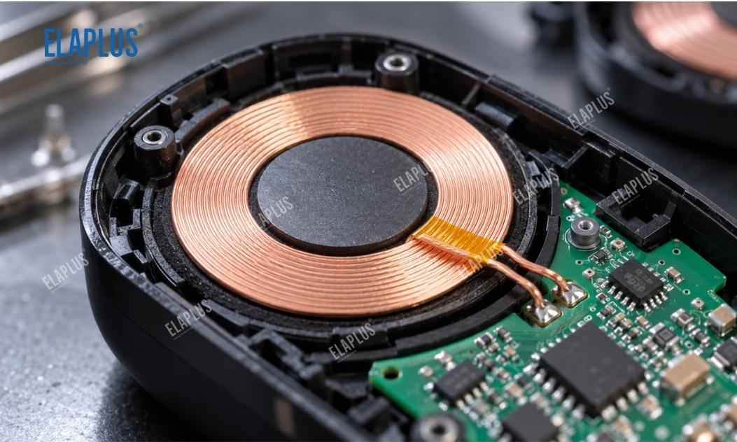
Electric shavers, electric toothbrushes, smart wearable devices and some industrial wireless power supply modules usually realise non-contact energy transfer via electromagnetic induction. There is a defined structural relationship among internal receiver coils, magnetic materials, rectifier circuits and charging control modules. Any shift in assembly position may affect the final system performance.
Some products charge normally in bare-board state, yet show longer charging duration, abnormal input power or increased temperature rise after potting, curing and housing assembly. At this stage, it is necessary to confirm whether the fault originates from electromagnetic coupling, power conversion or thermal management.
Why Wireless Charging Efficiency May Drop after Potting despite Normal Performance before Potting
Energy transfer efficiency of wireless charging is related to the coupling degree between transmitter and receiver coils. For inductive systems, coil clearance, lateral offset, tilt angle and magnetic material condition can all change magnetic flux coupling and the system operating point.
Before potting, the receiver coil may be fixed by plastic positioning posts, brackets or adhesive tapes. After potting, the coil may shift due to adhesive flow, assembly pressure or mechanical stress generated during curing.
Even if no obvious coil displacement occurs, the added thickness of the potting layer may change the distance between the receiver coil and the housing surface. If the total gap between the charging base and the device increases accordingly, the system coupling conditions will change.
Therefore, the core of wireless charging coil potting is not to fix the coil as rigidly as possible, but to maintain the designed electromagnetic structure while meeting protection requirements.
How to Distinguish Coil Offset, Magnetic Sheet Variation and Circuit Abnormality
Charging time alone cannot diagnose faults in wireless charging modules, since battery state of charge, thermal protection strategies and charging control logic also affect test results.
It is recommended to fix the charger, input voltage, battery condition and ambient temperature first, then compare electrical and structural parameters before and after potting.
| Fault Symptom | Priority Inspection Direction | Recommended Verification Method |
|---|---|---|
| Reduced charging power after potting | Coil clearance or lateral offset | Measure coil position and transmission power |
| Continuous abnormal temperature rise at the same location | Magnetic sheet position, local loss or structural interference | Inspect magnetic sheets and perform thermal distribution testing |
| Shift of resonant frequency | Variation of coil inductance and parasitic parameters | Measure inductance, impedance and resonant characteristics |
| Abnormality appears only after curing | Structural changes induced by curing | Compare coil height before and after curing |
| Fluctuating charging performance across batches | Variations in positioning, assembly and potting processes | Inspect fixtures, adhesive dosage and curing conditions |
| Normal temperature rise but slow charging | Changes in charging control or battery status | Check control strategy and charging curve |
If faults consistently appear at identical positions, positioning structures and assembly tolerances should be checked first. For random faults, further inspection of potting volume, fixture stability, curing conditions and production process variation is required.
Will Potting Adhesive Directly Block the Magnetic Field of Wireless Charging?
Conventional non-magnetic silicone or epoxy potting compounds do not block low-frequency alternating magnetic fields the way metal shielding does. It cannot be simply assumed that a thicker adhesive layer inevitably leads to higher magnetic loss.
Nevertheless, potting materials may change the dielectric environment around the coil and affect certain parasitic parameters. A more common and higher-priority verification target is whether the adhesive layer or assembly process alters the relative position between the coil and magnetic sheet.
If the potting material contains functional fillers, verify whether its formulation affects electromagnetic characteristics at the target operating frequency. For high-frequency or highly compact wireless power supply systems, conclusions shall be drawn from actual electromagnetic tests instead of material category alone.
Why Magnetic Sheet Position Changes Also Require Attention
Ferrite and other magnetic materials are commonly used at the receiver side of wireless charging to assist magnetic flux management. The gap, relative position and integrity of magnetic sheets and coils affect local magnetic field distribution.
If the magnetic sheet tilts, cracks or shifts position during potting, the system may still suffer coupling variation or increased local loss even when the receiver coil itself remains undisplaced.
Therefore, both coils, magnetic sheets, positioning brackets and potting layers should be examined during sample disassembly, rather than only checking whether the PCB is fully covered.
Silicone or Epoxy Potting Adhesive for Wireless Charging Modules?
Selection priorities differ between material systems. For compact wireless charging modules subject to vibration, drop and thermal cycling, mechanical restraint and bonding performance shall be evaluated together with the structure.
| Selection Criteria | Silicone Potting System | Epoxy Potting System |
|---|---|---|
| Mechanical Buffering | Usually preferred | Depends on specific formulation |
| Structural Fixation | Subject to adhesion and hardness | Generally for rigid fixation |
| Thermal Cycling Performance | Reduces stress risk via flexible buffering | Structural restraint needs close attention |
| Waterproofing and Insulation | Achievable by formulation | Achievable by formulation |
| Automated Potting | Matching mixing and curing process required | Matching mixing and curing process required |
| Wireless Charging Performance | Full module verification mandatory | Full module verification mandatory |
It cannot be generalised that silicone is always more suitable than epoxy for wireless charging. The key is to confirm whether the coil is stress-sensitive, whether the module requires robust mechanical fixation, and whether the assembly can stably retain coil position.
How to Choose between SIPA 3040 and EP 1702
ELAPLUS SIPA 3040 is a two-component addition-curing thermal conductive silicone potting compound with a 100:100 mixing ratio for A and B components. It features good flowability, cures at room temperature or under heating, and adheres to substrates including PC, PET, PA, PBT and some metals. Its operating temperature range is -60℃ to 200℃, making it a candidate for wireless charging coil potting and structural protection.
EP 1702 is a two-component epoxy potting compound curable at ambient temperature, characterised by low exotherm and low volume shrinkage during curing. It provides waterproof, moisture-proof and electrical insulation protection after curing. It can be shortlisted for structures prioritising rigid fixation and cost control, yet post-curing coil position and electromagnetic performance must be validated.
Neither material can be finalised merely based on waterproofing and insulation. Wireless charging modules also require verification of coil positioning, magnetic sheet condition, charging efficiency and temperature rise.
Why Potting Height Should Not Be Determined Solely by Remaining Housing Space
Wireless charging modules normally integrate receiver coils, magnetic sheets, PCBs, connecting wires and plastic positioning structures. Defining potting volume only by housing capacity may lead to excessively thick local adhesive layers or coil displacement during subsequent assembly.
The rational approach is to set potting height based on protection objectives, clarifying zones requiring continuous filling, reserved assembly clearance and surfaces where adhesive may interfere with mating features.
For height-sensitive receiver coil structures, measure the distance between the coil and housing reference plane before and after potting, and recheck after curing to ensure critical dimensions stay within design specifications.
Why Wireless Charging Performance Tests Are Mandatory for Mass Production Validation
Traditional potting validation mainly focuses on waterproofing, insulation, adhesion and curing state, while wireless charging modules have explicit electromagnetic functional requirements.
It is recommended to record input power, output power, charging duration and temperature at key locations before and after potting, using the same charger, identical battery condition and consistent ambient temperature. Meanwhile, inspect coil inductance, resonant state and structural relationship between magnetic sheets and coils.
For products requiring washability or long-term operation in humid environments, re-test charging performance after specified waterproof, thermal cycling and mechanical tests to confirm both material protection and system functionality meet requirements.
Industry Pitfall: Waterproof Rating Is Not the Only Factor for Wireless Charging Potting
The first misconception: good insulation of potting adhesive guarantees no impact on wireless charging performance. In fact, material insulation and overall electromagnetic coupling are two separate evaluation dimensions.
The second misconception: only record single-piece potting weight without checking the final position of coils and magnetic sheets. For compact structures, positional variation matters more than adhesive dosage.
The third misconception: replace materials immediately once slower charging is observed, without controlling battery state, charging base position and test conditions, resulting in incomparable test data among samples.
ELAPLUS selects adhesives based on working conditions rather than stacking performance parameters. For wireless charging modules, confirm the electromagnetic structure and fault mechanism first, then compare waterproofing, insulation, adhesion and mechanical buffering properties of materials, with final qualification based on full-module functional verification.
Application Guidance
SIPA 3040 silicone potting system can be prioritised for wireless charging modules of electric shavers, electric toothbrushes and other devices requiring waterproofing, insulation and mechanical buffering. EP 1702 epoxy system can be further evaluated for modules with defined structural fixation demands and stiffness requirements.
If the root cause lies in unreasonable positioning of transmitter and receiver coils or inherent defects of magnetic sheet structures, replacing potting adhesive alone will not solve the problem. Optimise the positioning structure first before material and process validation.
FAQ
Q: Does slower charging after wireless coil potting always result from adhesive interfering with the magnetic field?
A: Not necessarily. Check coil clearance, lateral offset, magnetic sheet condition and charging control conditions first, then assess material influence on electromagnetic parameters.
Q: Can thermal conductive potting adhesive be used for wireless charging modules?
A: Yes, but its insulation, mechanical compatibility and electromagnetic adaptability must be confirmed. Qualified thermal conductivity cannot replace full-module charging efficiency verification.
Q: Is SIPA 3040 applicable for wireless charging coil potting?
A: It is a candidate material. This two-component silicone system offers protection, adhesion and mechanical buffering, yet validation on actual modules is required for individual projects.
Q: Are softer adhesives always better for wireless charging applications?
A: Not necessarily. Soft materials help reduce mechanical restraint, while coil positioning stability, assembly requirements and service environment are equally important.
Q: How to judge whether potting process affects wireless charging performance?
A: Compare coil position, inductance parameters, charging power, efficiency and temperature rise before and after potting under identical test conditions, and identify root causes together with structural inspection.
Previous post: Why Does the Electromagnetic Flowmeter Transmitter Fill with Moisture, Darken or Even Blacken? Do Not Only Focus on IP Rating — Check Condensation Paths and Display Area Encapsulation First
Next post: What Adhesive to Use for Sealing between Glass and Aluminum Housing of Underwater LED Lights? For One-Part Silicone, Focus on Seal Gap and Curing Path