When poor relay contact performance or unstable test results occur after conformal coating, priority should be given to checking whether the coating has migrated into electrical contact interfaces, as well as issues with masking, cleaning and rework processes. Conformal coating is designed to protect circuit boards and electronic components, rather than covering all conductive areas. Clear boundaries must be defined between protection coverage and electrical functions for relay contacts, pluggable terminals, test points and zones requiring reliable electrical connections.
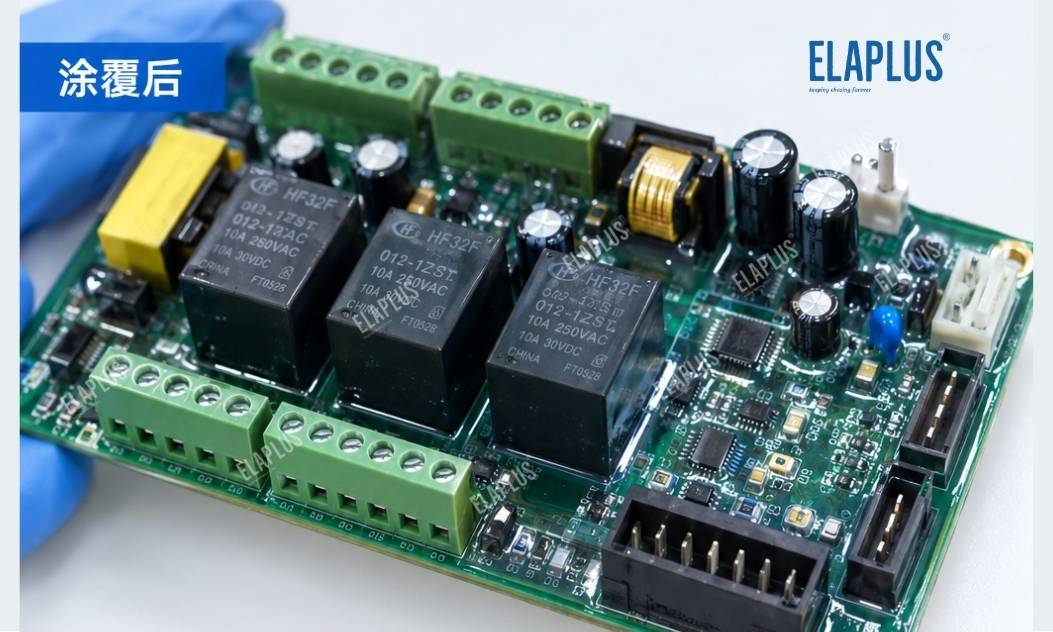
Industrial controllers, PLCs, relay control boards and power control modules normally contain numerous solder joints, connectors, relays and test interfaces. Conformal coatings reduce the impact of moisture and contaminants on circuits. However, improperly controlled coating paths, masking positions or rework operations may contaminate contact interfaces and increase the difficulty of subsequent inspection and maintenance.
Therefore, if electrical tests pass before coating but contact anomalies appear afterwards, replacing the conformal coating material immediately is not recommended. A more reasonable approach is to identify the affected electrical interface first, then distinguish coating intrusion, residual contamination, connector assembly defects and inherent circuit failures.
Why Does Poor Contact Occur after Conformal Coating?
The protective film formed by conformal coating is insulating and suitable for circuit zones requiring moisture resistance, contamination protection and electrical isolation. Nevertheless, relay contacts, pluggable terminals and other interfaces for direct electrical conduction are not suitable for continuous coating coverage.
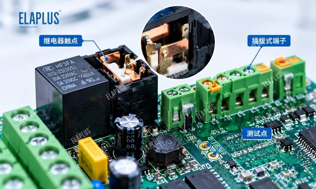
No-Coating Zones for Conformal Coating
Incomplete masking may allow coating material to spread near contacts or mating areas. Even if no obvious film is visible on the surface, the contact interface may still be affected. Tiny residues and changes to contact surface conditions can interfere with low-level signals or raise contact resistance.
On the other hand, post-coating contact anomalies do not always mean the coating has directly covered the contacts. If failures are concentrated on a specific connector or workstation, terminal assembly, solder joint condition, cleaning procedure and test fixtures should also be checked, to avoid attributing faults from different root causes to material issues.
How to Tell Coating Intrusion, Residual Contamination and Connector Failures Apart?
It is recommended to compare electrical readings of the same PCB before and after coating and judge the root cause based on failure locations. For random contact faults, focus on masking, spray paths and operator procedures. For repeated failures at identical contacts or structural positions, review design boundaries and masking fixtures first.
| Failure Symptom | Primary Inspection Direction | Recommended Verification Method |
|---|---|---|
| Increased contact resistance after coating | Coating intrusion or surface contamination | Inspect contact zones and retest contact resistance |
| Recurring failures at the same location | Improper masking boundary or coating path design | Check masking fixtures and spray coverage |
| Random failures across workstations | Operator variation, spray parameter drift or inconsistent cleaning | Compare process records from different stations |
| Test points cannot be accessed after coating | Test point coverage or changed probe contact conditions | Review no-coating requirements for test points and test methods |
| Worsening contact performance after rework | Inadequate cleaning or mechanical damage | Inspect residues, terminal surfaces and solder joints |
| Intermittent electrical faults after humidity exposure | Insufficient coating coverage or contaminant residues | Verify protection boundaries, contamination and insulation status |
Judgement should not rely solely on visual appearance of the coating. Clear coatings make faint residues hard to detect, and abnormal contact resistance can also stem from terminal spring properties, plating quality or assembly issues. Comprehensive assessment combining electrical testing and local inspection is required.
How to Select Conformal Coating Materials for Industrial Control Boards?
Material selection shall consider protected objects, coating methods, curing conditions and future maintenance requirements simultaneously, instead of only comparing surface dry time or coating hardness.
| Material System | Key Considerations | Suitable Application Direction |
|---|---|---|
| Silicone Conformal Coating | Flexibility, thermal cycling resistance, insulation and moisture resistance | Electronic circuits and components requiring flexible protection |
| Acrylic Conformal Coating | Coating process, curing efficiency and repairability | PCBs balancing production efficiency and maintainability |
| Polyurethane Conformal Coating | Chemical resistance, adhesion and curing conditions | Circuit boards with defined requirements for harsh chemical environments |
Actual performance of each system depends on formulation and product specification. Material grade alone cannot determine superiority. For industrial control boards operating under long-term temperature fluctuation, vibration or humid conditions, validation shall be carried out on real substrates, specified coating thickness and target working conditions.
What Types of Industrial Control Boards Fit COATING 9061?
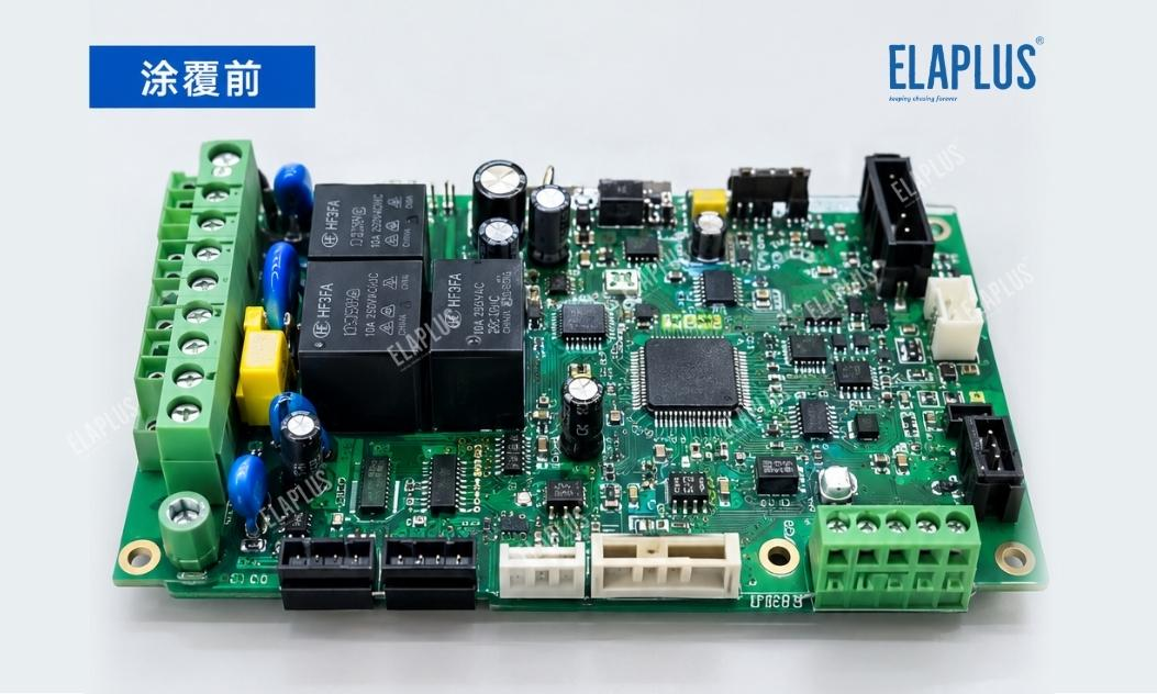
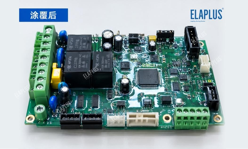
ELAPLUS COATING 9061 is a low-viscosity single-component silicone conformal coating applicable via spraying, dipping, brushing or potting. It forms a transparent film with fluorescent tracer additive for protection of electronic components, ICs, thick-film circuits and printed circuit boards.
COATING 9061 can be shortlisted for industrial control boards where PCB surfaces, solder joints and electronic components need protection while relay contacts, pluggable terminals and test points must remain functional. During application, no-coating zones shall be defined according to the electrical layout, and the coating shall be validated for moisture resistance, insulation and environmental compatibility.
The core principle is not to apply thicker coating everywhere, but to form continuous coverage on zones requiring protection while ensuring electrical contact interfaces are free from unintended coating.
How to Establish Reliable Coating and Masking Processes?
Coating procedures should be planned at the PCB layout stage, rather than relying on manual remedial work during mass production. Designers shall specify relay contacts, connector mating surfaces, test points, switch operating areas and other no-coating locations. Masking methods, coating scope and acceptance criteria shall be documented in process specifications.
For mass production, the following validation workflow is suggested: record key electrical parameters before coating; perform masking and coating per formal procedures; inspect coating boundaries after curing and retest contact resistance, insulation performance and functional indicators defined for the product. Fluorescent inspection and magnified local observation may be used for questionable areas, but fluorescent inspection alone does not prove electrical reliability.
If rework is required, procedures for coating removal, cleaning and retesting shall be defined to prevent mechanical scraping from damaging contact plating, pads or traces. For products with existing contact faults, test records before and after rework shall be retained to confirm fault elimination.
Industry Pitfall: Full Coating Coverage Does Not Equal Higher Board Reliability
A common misconception is that conformal coating means uniform coverage over the entire board. In fact, both coating integrity and electrical functionality must be satisfied. Clear process boundaries are required for contact interfaces, test zones and areas for subsequent assembly.
Another easily overlooked point is checking coating coverage without retesting critical electrical parameters after coating. Even a visually uniform coating cannot guarantee that relay contacts, terminals and test interfaces remain unaffected.
ELAPLUS selects adhesives based on working conditions rather than stacking performance parameters. For industrial control boards, a sound protection scheme starts by separating protected zones and no-coating zones, then selects materials and application methods according to the actual structure, and finally validates reliability by comparing electrical performance before and after coating.
Application Guidance
Silicone conformal coatings such as COATING 9061 may be evaluated for industrial control boards requiring moisture and contamination protection while keeping relays, connectors and test interfaces operational. For boards with high-density connectors, fine-pitch contacts or complex shadowed structures, selective coating, local masking and automated path control need further assessment.
If products operate continuously in high-humidity, salt spray or special chemical environments, coating protection performance shall be verified under real working conditions. If frequent maintenance is expected, coating removal, local touch-up and post-rework electrical testing must be embedded into process design instead of focusing only on the initial coating result.
FAQ
Q: Should I change the coating material immediately after seeing poor relay contact after conformal coating?
A: No. First check accidental coating on contacts, masking completeness and surface residues, then troubleshoot terminals and assembly issues.
Q: Can clear conformal coating affect electrical contact?
A: It will impair contact performance if it enters conductive mating interfaces. Therefore, no-coating specifications shall be defined for contacts and connector mating surfaces according to product design.
Q: Can COATING 9061 be used on industrial control boards?
A: This product is formulated for conformal protection of electronic components, ICs, thick-film circuits and PCBs. Suitability shall be validated against circuit layout and target operating conditions.
Q: How to confirm a conformal coating process is qualified?
A: Visual inspection alone is insufficient. Coating boundaries must be checked, and contact resistance, insulation performance and key functions shall be tested as specified.

Previous post: Why Low-Temperature Cure Adhesives Are Preferred for CCD/CMOS Frame Bonding in Camera Modules: Speed Is Not the Priority — Thermal Process Load Control Matters
Next post: Why Does the Electromagnetic Flowmeter Transmitter Fill with Moisture, Darken or Even Blacken? Do Not Only Focus on IP Rating — Check Condensation Paths and Display Area Encapsulation First