When excessive unbalance, rising vibration or abnormal noise occurs on motor rotors after magnet bonding, priority shall be given to checking magnet mass distribution, bond-line thickness, circumferential squeeze-out, rotor concentricity and cured assembly position, instead of immediately concluding insufficient structural bond strength. For robot joint motors, industrial servo motors and high-speed brushless motors, magnet bonding must deliver structural reliability while preventing mass distribution changes caused by inconsistent adhesive dosage and assembly deviation.
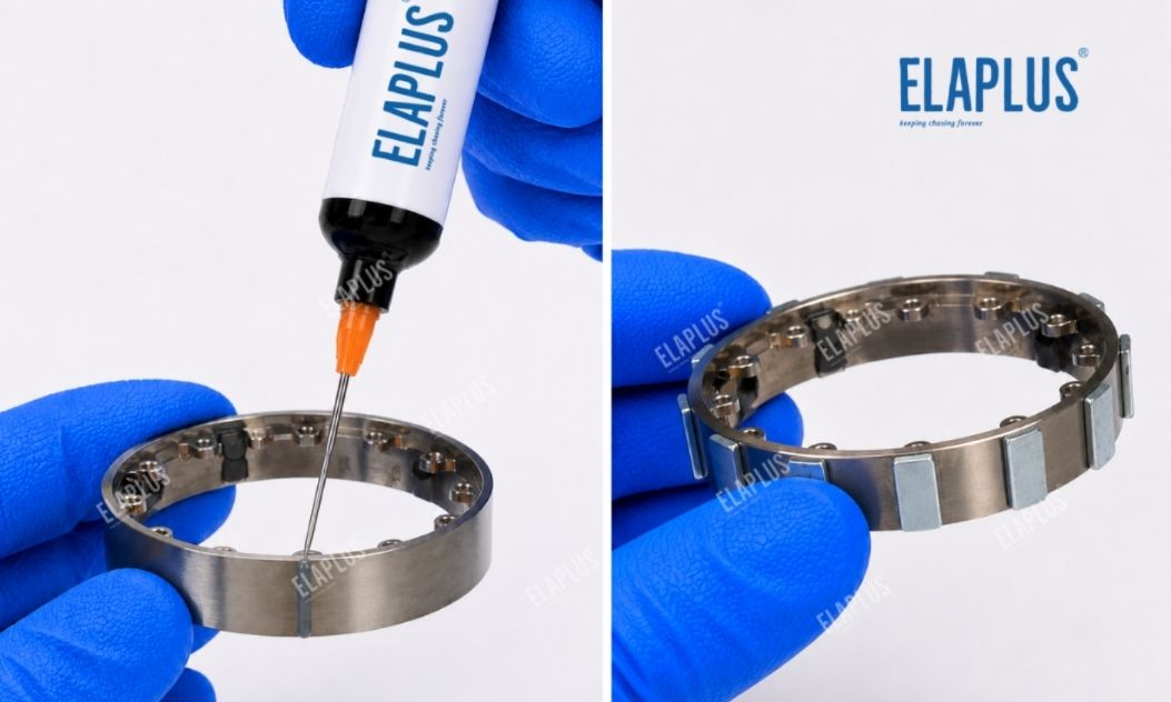
Permanent magnet motor rotors generally consist of rotor core, magnets, shaft and required retention features. Once magnets are installed with adhesives or hybrid fastening methods, bond-line thickness and magnet placement affect rotor geometry, and local adhesive variation alters rotating mass distribution.
Therefore, acceptable bonding and acceptable dynamic balance are two separate engineering judgements. Bond strength tests evaluate joint reliability, but cannot replace rotor runout, mass distribution and dynamic balance tests.
1. Why Does Unbalance Occur after Magnet Bonding?
Under high-speed rotation, uneven mass distribution generates periodic centrifugal excitation. Deviations in magnet installation position, bond-line thickness or rotor geometry may shift the centre of mass away from the rotational axis and worsen vibration.
During magnet assembly, inconsistent adhesive volume under individual magnets or excess adhesive squeezed and accumulated at a certain circumferential position changes cured mass distribution. For precision motors with small rotor diameter and high rated speed, even minor local mass variation must be assessed against dynamic balance requirements.
Unbalance is not necessarily caused by the adhesive itself. Magnet mass tolerance, shaft eccentricity, core dimensional deviation, fixture error and bearing condition all affect test results. Phased inspection is required to locate the root cause.
2. How to Distinguish Issues from Adhesive Volume, Magnet Assembly and Rotor Geometry?
It is recommended to record the baseline geometry of the rotor core before magnet mounting, inspect position and clearance after magnet fitting, and measure runout and dynamic balance after full cure. Comparison across manufacturing stages identifies whether the anomaly originates from the bonding process.
| Symptom | Priority Inspection Items | Diagnostic Method | Improvement Direction |
|---|---|---|---|
| Unbalance rises after cure | Adhesive distribution, magnet positional shift | Compare mass and position before and after cure | Optimise metering and positioning |
| Repeated failure at the same circumferential zone | Magnet dimension, locating slot, local squeeze-out | Inspect fixed location and cross-section | Improve dimensional tolerance control |
| Excessive rotor radial runout | Shaft assembly, core or magnet eccentricity | Measure radial runout and concentricity | Calibrate assembly reference |
| Random out-of-tolerance across parts | Shot volume, assembly and cure fluctuation | Audit equipment and process logs | Improve process consistency |
| Unbalance drifts after correction | Balance weight retention, structural stability | Recheck weight location and condition | Validate correction procedure |
| Abnormal vibration at high speed | Unbalance, bearing or electromagnetic excitation | Vibration spectrum and full motor test | Separate mechanical and electromagnetic sources |
If defects repeatedly appear at the same magnet station, inspect rotor structure, locating slots and dispensing path first. If failures occur randomly across batches, audit adhesive dosage, mixing, assembly fixtures and curing conditions.
3. How Does Bond-Line Thickness Affect Magnet Position?
The adhesive layer between magnets and rotor core not only provides bonding, but also determines the final mounting height of magnets. Without effective mechanical locating, thickness variation introduces radial or axial positional offset between magnets.
For surface-mounted permanent magnet rotors, inspect the bond layer under magnets, gaps between adjacent magnets and magnet slippage during cure. For interior permanent magnet structures, focus on slot clearance, end stop features and unintended adhesive migration.
Thinner bond lines are not always better, nor does a thicker layer guarantee higher reliability. The proper joint gap is defined by substrate surface condition, bond strength, dimensional tolerance and operating conditions. The effective bond thickness required for structural integrity shall not be arbitrarily reduced merely to improve dynamic balance.
4. Distinguish Magnet Structural Bonding and Dynamic Balancing
Magnet bonding and dynamic balance correction are separate manufacturing operations, and material functions must be clearly defined.
| Process Item | Core Objective | Candidate Material | Key Validation Items |
|---|---|---|---|
| Magnet-to-core structural bonding | Secure magnet retention | Epoxy structural adhesive | Shear, peel resistance, thermal and vibration performance |
| Local balance weight addition | Adjust rotor mass distribution | Balancing compound | Weight dosage, cure and long-term retention |
| Magnet assembly locating | Control position and joint gap | Fixture together with bonding process | Spacing, runout, concentricity |
| Final dynamic balance inspection | Confirm rotating mass distribution | Dynamic balancing tester | Residual unbalance |
| Full-speed running test | Evaluate system stability | Complete rotor-bearing assembly | Vibration, temperature rise, noise |
Structural adhesive is not equivalent to balancing compound. For rotors with magnet offset, structural damage or bonding defects, resolve structural issues before dynamic balance correction. Weight addition shall not be used to mask underlying defects.
5. Suitable Applications for EP 2029 and UV 1020
ELAPLUS EP 2029 A/B is a two-component high-temperature resistant epoxy structural adhesive for motor magnets and metal components. Mix ratio by weight is 100:50. It can be cured at ambient or elevated temperature; the cure profile shall be confirmed based on bond thickness and assembly conditions.
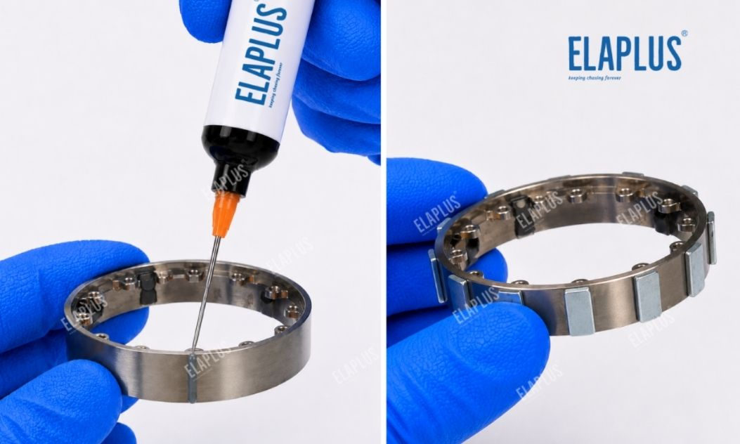
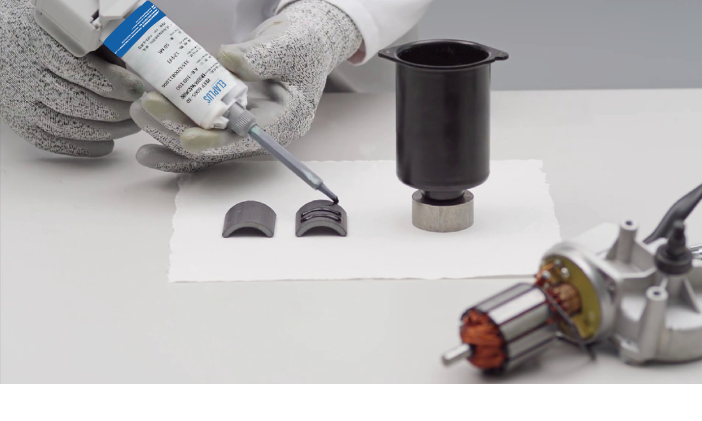
For magnet bonding, evaluate adhesion of EP 2029 to magnet surfaces, rotor cores and surface treatment layers. Verify dimensional stability and long-term joint reliability on actual rotors.
UV 1020 is an UV-curable acrylic adhesive designed for dynamic balance trimming of motor rotors, cooling fans and other rotating parts. It cures rapidly under UV irradiation and is intended for local weight correction at positions identified by unbalance measurement.
Note that cure performance of UV 1020 depends on light source, irradiation angle, bond thickness and shadowing features. For areas shielded by metal or thick weight beads, validate through-cure and weight retention on test coupons; surface tack-free condition alone does not indicate full cure.
ELAPLUS: Select adhesives based on service conditions, not just stack parameters. EP 2029 is for structural magnet joining, while UV 1020 is a candidate for dynamic balance trimming. They cannot be interchanged simply because both have adhesive properties.
6. Consistency Control for Automatic Dispensing and Magnet Assembly
Before magnet bonding, confirm core surface, magnet dimension and locating features meet design requirements, and check contamination and surface pretreatment. For two-component epoxy, precisely control mix ratio, shot volume and pot life.
For automatic dispensing, design the bead path according to magnet length, contact area and target joint gap. Ensure uniform coverage after compression and avoid heavy adhesive buildup at one end. Assembly fixtures control magnet radial position, axial height and inter-magnet spacing and maintain stability throughout curing.
After cure, inspect magnet position, circumferential squeeze-out, outer diameter and radial runout. For rotors requiring balance trimming, confirm structural bonding and assembly quality before unbalance measurement.
7. Validate Long-Term Stability after Dynamic Balance Correction
Prepare test coupons with production BOM rotors, magnets, shafts and adhesives. Record readings before bonding, after cure and after balance trimming. Weight location and dosage shall be determined by the unbalance vector from measurement instead of visual judgement.
After UV balancing compound cures, re-measure residual unbalance and inspect bead adhesion, profile and surrounding mechanical clearance. For high-speed motors, validate weight retention under maximum speed, temperature cycling and vibration.
If unbalance drifts repeatedly after trimming, check balancing bead adhesion, rotor structure and fixturing repeatability. Full motor running test shall be performed only after stable mass distribution and secure bonding are confirmed.
8. Adaptation for Robot Joint Motors and High-Speed Fans
Robot joint motors demand low vibration, stable position control and smooth operation. Focus on magnet locating accuracy and interaction between rotor balance and bearing systems. For high-speed brushless motors, minor local mass deviation creates obvious vibration at high rpm, which shall be evaluated against design speed and allowable residual unbalance.
AI server cooling fans and industrial high-speed fans also require dynamic balance control, but impeller material, weight placement and cure conditions differ from motor magnet assemblies. When using UV 1020 for these fans, revalidate performance based on substrate, UV accessibility and operating environment.
FAQ
Q: Is excessive unbalance after magnet bonding always caused by inconsistent adhesive volume?
A: No. Magnet mass tolerance, rotor runout, concentricity and assembly position should also be checked.
Q: Can EP 2029 be used for motor magnet bonding?
A: It can be used as a candidate structural adhesive, subject to validation of adhesion, cure and operational reliability on target magnets and cores.
Q: Can UV 1020 replace structural magnet-bonding adhesive?
A: Direct substitution is not allowed. UV 1020 is primarily intended for dynamic balance trimming of rotating parts; structural bonding must be qualified separately.
Q: Is further testing required after dynamic balance correction?
A: Residual unbalance must be re-tested, and weight retention must be verified under operating temperature, speed and vibration.