Degraded insertion loss, shifted resonant frequency or reduced high-frequency suppression capability of EMI filters after potting shall not be directly attributed to insufficient insulation performance of potting adhesive. Priority shall be given to investigating changes in parasitic capacitance before and after potting, magnetic core stress, component displacement and discrepancies in test conditions. For high-frequency filters, dielectric properties of materials, post-curing mechanical restraint and actual potting structure deserve more attention than hardness or thermal conductivity alone.
EMI filters are widely used in industrial power supplies, PV inverters, energy storage PCS, servo drives, communication power supplies and other equipment. They generally contain common-mode inductors, differential-mode inductors, X/Y capacitors and associated interconnections. Potting materials provide insulation protection, component fixation and environmental shielding.
Some products meet design requirements on bare-board testing, yet their insertion loss curves shift across certain frequency bands after potting. Especially when new resonant peaks, reduced attenuation or batch fluctuations appear at high frequencies, engineers need to distinguish whether the filter’s electrical parameters have changed, or the measurement results are altered by the test environment and assembly status.
Why High-Frequency Performance May Change after Filter Potting
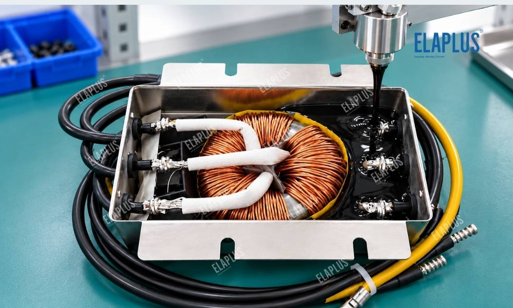
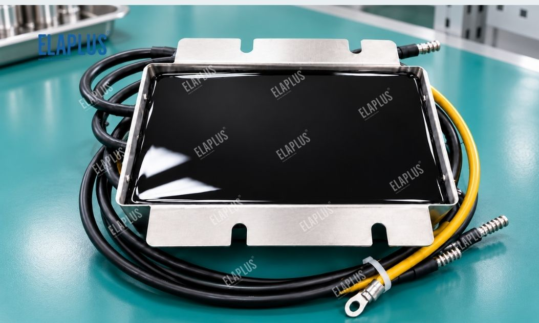
The actual frequency response of a filter depends not only on nominal inductance and capacitance values, but also on winding-to-winding parasitic capacitance, stray capacitance between components and metal housings, as well as lead layout.
Before potting, the space between some conductors is mostly filled with air. After potting, the dielectric environment changes. If the relative permittivity of the potting material differs from air, local stray capacitance may vary, which further affects high-frequency resonance and impedance characteristics.
This effect does not mean all potting compounds will significantly degrade filtering performance. The magnitude of variation depends on material dielectric properties, potting location, conductor spacing and the original frequency design of the filter.
Therefore, material selection for high-frequency EMI filter potting must account for dielectric environment variation instead of focusing merely on dielectric strength.
How to Distinguish Anomalies Caused by Parasitic Capacitance Changes and Magnetic Core Stress
Both mechanisms can impair filter performance, yet they show different symptoms and require different troubleshooting methods. Parasitic capacitance variation tends to affect high-frequency response, while mechanically restrained magnetic cores may experience changes in effective permeability and relevant inductance parameters if the magnetic material is stress-sensitive.
| Symptom after Potting | Possible Cause | Preferred Verification Method |
|---|---|---|
| Reduced high-frequency insertion loss | Variation of parasitic capacitance | Compare high-frequency impedance and insertion loss |
| Shifted resonant frequency | Altered distributed parameters | Measure impedance spectrum |
| Changed low-frequency inductance | Magnetic core stress or structural variation | Compare L values before and after potting |
| Markedly increased high-frequency loss | Variation of dielectric loss or magnetic loss | Isolate the influence of material and magnetic core |
| Parameter drift under temperature change | Temperature coefficient and structural stress | Retest under constant temperature |
| Large discrepancy between batches | Fluctuations in potting position or process | Check adhesive dosage, component placement and curing process |
Note that insertion loss is a test result of the entire filter assembly. A single curve cannot confirm a defect in a specific material parameter.
For common-mode inductors, distinguish between common-mode and differential-mode test conditions. For filter networks with multiple capacitors and inductors, analysis shall follow the actual circuit topology.
Why Dielectric Constant of Potting Material Matters
Dielectric constant describes the polarisation behaviour of a material under an electric field. For structures with closely spaced conductors operating at high frequencies, changes in surrounding dielectric media can modify parasitic capacitance and disrupt the original frequency response of the filter.
Nevertheless, a low dielectric constant does not automatically guarantee better filter performance. Dielectric loss, temperature and frequency dependence, as well as the actual filling area of the material, must also be considered.
For example, material wrapping only the outer housing of the filter exerts a completely different effect on parasitic parameters compared with material filling the gaps between dense windings and high-potential conductors.
The key is to verify the dielectric behaviour of the material at the target frequency and identify which electric-field-sensitive zones the material enters.
Why Magnetic Core Stress Can Also Alter Filter Parameters
Some soft magnetic materials are stress-sensitive. After curing, potting compounds may form strong mechanical confinement, subjecting the magnetic core to continuous compression or other stress and degrading magnetic properties.
For filters using ferrite, nanocrystalline and other magnetic materials, inspect not only whether the adhesive cracks, but also whether the magnetic core condition changes after curing.
If low-frequency inductance shifts noticeably after potting, and high-frequency parasitic parameter variation cannot fully explain the phenomenon, further inspect the magnetic core mounting method and mechanical restraint imposed by the potting material.
This is why certain filters are better candidates for flexible potting systems rather than rigid epoxy compounds.
Comparison among Epoxy, Polyurethane and Silicone Potting Compounds
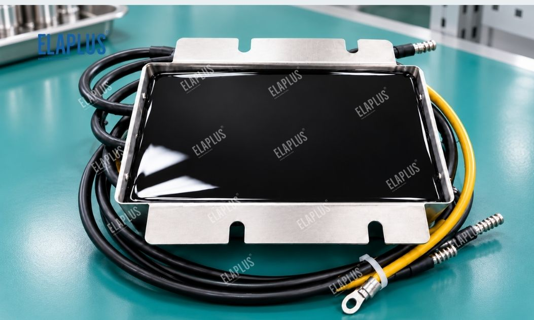
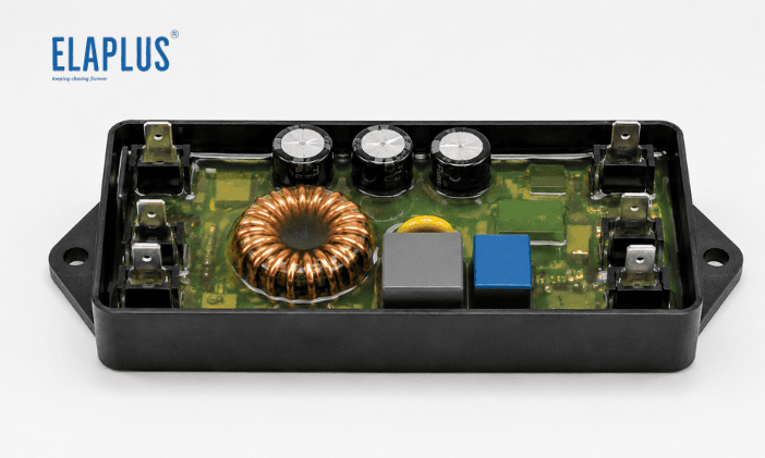
All three systems are suitable for electronic encapsulation, yet they differ in mechanical restraint, environmental resistance and processing characteristics.
| Material System | Key Selection Features | Application Notes for EMI Filters |
|---|---|---|
| Epoxy Potting Compound | High structural strength and fixation capability | Watch magnetic core stress and curing process |
| Polyurethane Potting Compound | Tunable flexibility via formulation | Verify dielectric properties and long-term environmental compatibility |
| Silicone Potting Compound | Excellent flexibility and stress buffering | Check dielectric parameters of the specific grade |
| Low-Stress Silicone Gel | Low mechanical restraint for sensitive structures | Not a direct substitute for load-bearing structural adhesive |
Flexible silicone systems are usually prioritised for magnetic cores sensitive to stress. If high mechanical fixation strength is required, compare other systems according to structural design.
Material selection cannot be separated from operating frequency, magnetic core material and potting location.
Why SIPA 1850 Is Worth Validating for Filter Potting
ELAPLUS SIPA 1850 is a two-component silicone potting system with a 1:1 mixing ratio. It features good flowability, insulation protection and flexible encapsulation for filters and other electronic components.
The SIPA 1850 series offers options with different thermal conductivity grades. Among them, SIPA 1850-15# with thermal conductivity of 1.5 W/m·K is suitable for thermally conductive potting of inductors, balancing insulation protection and mechanical buffering.
For EMI filters, SIPA 1850 shall not be evaluated solely by thermal conductivity. It is more critical to verify post-curing mechanical restraint, dielectric environment shift and frequency response using the actual magnetic core and filter circuit.
Especially for high-frequency applications, electrical performance of the specific grade at target frequency bands must be measured. Insulation performance tested at other frequencies cannot be equated to high-frequency filtering performance.
Why the Same Potting Compound May Yield Completely Different Test Results on Different Filters
Structural differences between filters often outweigh differences between materials. Common-mode inductors, differential-mode inductors, LC filter networks and multi-stage EMI filters differ greatly in winding layout, component spacing and electric field distribution.
Even with the same material, parasitic capacitance and mechanical restraint change when the potting height rises from the bottom of the core to full winding coverage.
Therefore, mass production finalisation cannot rely on one universal material test report. Establish a correlation among potting structure, adhesive dosage and electrical performance.
How to Design the Validation Workflow before Mass Production
Group tests shall be conducted on filters from the same batch. Record key electrical performance before potting, after potting and after environmental ageing. Keep test fixtures, lead length, test frequency and temperature consistent during measurement, so measurement system errors are not misinterpreted as material effects.
For structures suspected of parameter drift induced by curing stress, prepare control samples subjected to the same thermal profile without potting, to separate thermal effects from mechanical restraint of the material.
For structures suspected of dielectric environment variation, focus on high-frequency impedance curves and resonant positions, and analyse together with material dielectric characteristics.
Isolate failure mechanisms through controlled experiments before deciding whether to switch materials; this approach is usually more effective than simply upgrading material specifications.
Common Pitfalls: Insulation and Flame Resistance Are Not the Only Criteria for Filter Potting
- Misconception: Higher breakdown voltage means better high-frequency filtering performance. Dielectric strength reflects the material’s ability to withstand electric fields and cannot replace tests on dielectric constant, dielectric loss and overall frequency response.
- Misconception: Unchanged inductance after potting means electrical performance remains unaffected. Variation of high-frequency parasitic capacitance can still alter resonance and insertion loss.
- Misconception: Flexible materials have no impact on magnetic cores. Flexible materials reduce the risk of mechanical restraint, yet the final effect still depends on adhesive dosage, structure and magnetic core material.
- Misconception: Only test finished potted units without retaining baseline data before potting. Without side-by-side comparison, it is difficult to pinpoint at which process stage parameter drift occurs.
Application Guidance: Which Filters Suit Flexible Silicone Potting?
Flexible SIPA 1850 silicone potting system can be prioritised for filter inductors in industrial power supplies, servo drives, communication power supplies and inverters, where insulation protection, environmental sealing and minimised mechanical stress on magnetic cores are the main requirements.
If the filter relies on potting material to bear substantial structural loads, or faces explicit high-temperature, chemical medium and special electrical requirements, re-evaluate epoxy, polyurethane or other dedicated material systems.
For filters highly sensitive to high-frequency characteristics, confirm whether the potting material intrudes into critical electric-field zones. If necessary, reduce parasitic parameter variation via partial potting, adjusted potting height or structural optimisation.
ELAPLUS selects adhesives based on service conditions instead of stacking performance parameters. For EMI filters, first identify the frequency band where drift occurs, distinguish dielectric effects, core stress and process fluctuation, then finalise the material with real BOM and full-unit testing.
FAQ
Q: Why does insertion loss change after EMI filter potting?
A: Potting may alter the dielectric environment between conductors, parasitic capacitance and mechanical state of the magnetic core, thus changing frequency response. Determine the root cause via impedance and insertion loss comparison before and after potting.
Q: Does unchanged inductance mean potting has no influence?
A: Not necessarily. Normal low-frequency inductance does not rule out shifts in high-frequency parasitic capacitance and resonance characteristics.
Q: Should flexible potting adhesive be the first choice for EMI filters?
A: Flexible systems are preferred if the magnetic core is stress-sensitive, while insulation, environmental protection and mechanical fixation requirements must also be satisfied.
Q: Can SIPA 1850 be used for filter potting?
A: It is a candidate potting material for filters. SIPA 1850 is a two-component silicone potting system, and the specific grade shall be validated against filter structure and operating frequency.
Q: Why do high-frequency filters require dielectric parameter testing?
A: Material dielectric properties affect parasitic capacitance and loss between conductors, and high-frequency circuits are highly sensitive to such changes.
Previous post: Slower Response of NTC Temperature Sensor after Encapsulation? Check Adhesive Thermal Resistance and Probe Structure First before Replacing the Thermistor
Next post: Waterproof Gel for Optical Fiber Splice Closures Requiring Repeated Opening for Maintenance? Self-Healing Does Not Mean Unlimited Reusability