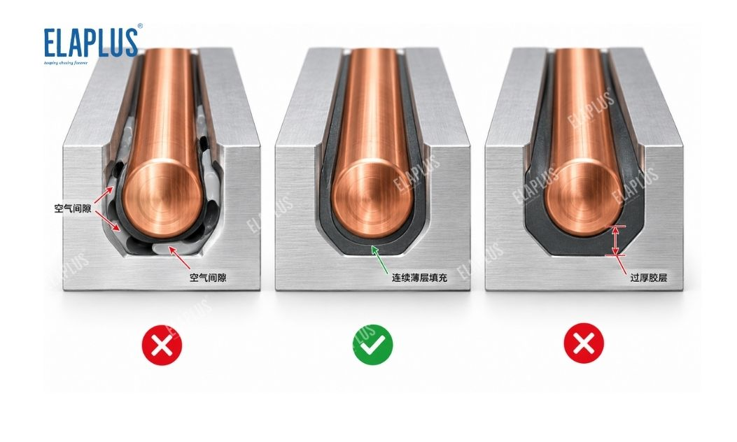
The core purpose of adhesive for embedded copper tubes in cold plates is not simply filling the clearance around copper tubes. It aims to minimise air gaps between tubes and the base plate, enable the adhesive to conform continuously to both copper tubes and substrates, while balancing thermal conductivity, bonding strength, temperature resistance and stability under thermal cycling. If adhesive is only piled on top of the copper tube and fails to flow into both sidewalls and the bottom of the groove, it may look fully filled externally, yet the thermal path is still interrupted by trapped air layers.
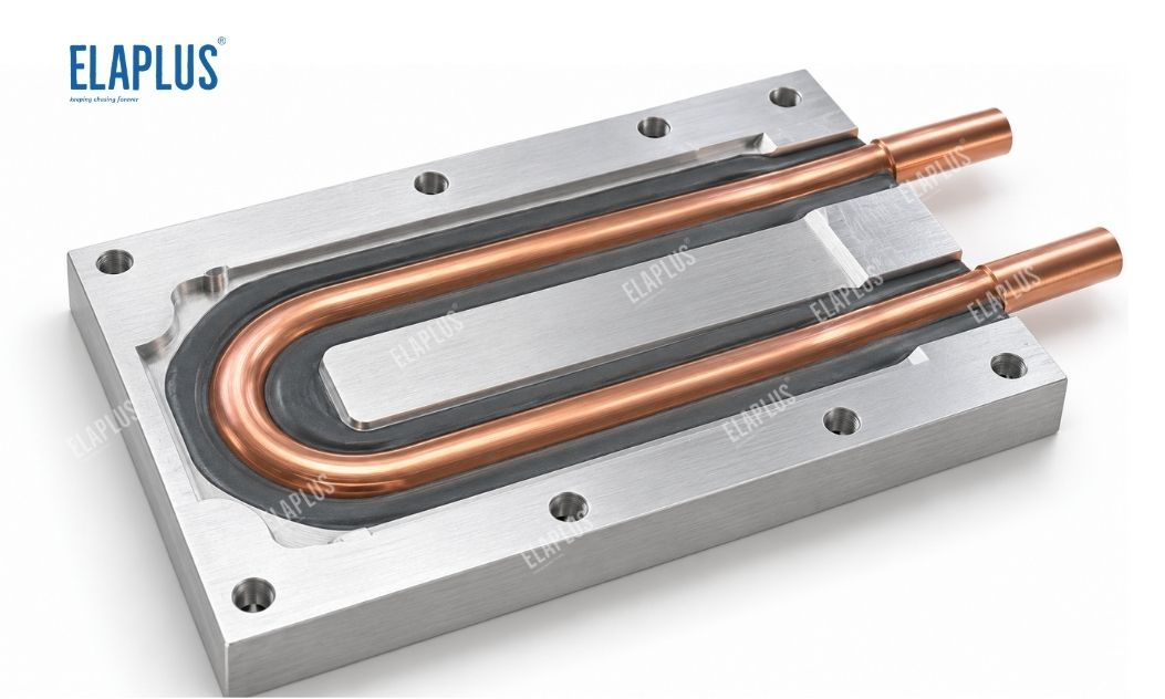
Heat transfer of cold plates with embedded copper tubes follows this route: Coolant → Copper Tube → Interface → Base Plate.
The most frequently overlooked part is the annular interface between copper tube and base plate.
Why Interface Treatment Is Still Required Even When Copper Tubes Are Pressed Into Aluminum Plates
Mechanical assembly does not guarantee 100% surface contact between copper tubes and grooves. Practical manufacturing tolerances and defects include:
- Copper tube roundness deviation
- Groove dimensional tolerance
- Local warpage
- Assembly clearance
- Surface roughness
After seating the copper tube into the groove, some areas may contact aluminum directly while tiny air gaps remain elsewhere. Air significantly raises interfacial thermal resistance. Therefore, the embedded-tube adhesive converts discontinuous mechanical contact into a nearly continuous thermally conductive contact.
Why Dispensing Only a Bead on Top of the Copper Tube Offers Limited Performance
Critical voids often do not appear on the top surface. They tend to form at:
- Copper tube sidewalls
- Fillet radius at groove bottom
- Transition zones between tube wall and groove
If the material is overly thixotropic and hardly flows after being dispensed on top, heavy adhesive builds up on the upper surface while voids remain on both sides. Visually the adhesive seems sufficient, but cross-section inspection reveals insufficient filling in the zones that matter most.
Desirable Flow Behaviour for Embedded-Tube Adhesive
Neither extremely low viscosity nor extremely high viscosity is ideal.
The optimal characteristic: stable coverage over copper tubes during dispensing, flow into side clearances after pressing or scraping, without uncontrolled overflow outside the target zone.
| Material Behaviour | Outcome | Primary Risk |
|---|---|---|
| Too fluid | Rapid run-off | Difficult dosage control |
| Too viscous | Stays on top | Poor sidewall filling |
| Moderate flow | Can be pressed into gaps | Favours continuous interface formation |
| Excessive adhesive build-up | Looks intact on surface | Over-thick bondline or local voids with bare copper exposed, discontinuous interface |
The process window for cold plate embedding must combine flowability, dispensing dosage and scraping pressure.
Why a Thicker Adhesive Layer Does Not Equal Better Thermal Conduction
Thermally conductive compounds inherently have thermal resistance.
For a given material with fixed thermal conductivity, a longer heat transfer path generally brings higher interfacial resistance. The ideal state is not creating an unnecessarily thick adhesive layer between copper tube and aluminum plate, but filling air voids with just enough material while maintaining a reasonable effective bondline thickness. Hence thermal conductivity value alone is insufficient for cold plate adhesive selection; cured bondline thickness must also be evaluated.
Why Thermal Cycling Must Be Considered for Copper‑Aluminum Interfaces
Cold plates undergo cyclic operation: Start-up → Temperature rise → Coolant circulation → Shutdown & cooling
Copper tubes, aluminum plates and cured adhesive expand at different rates. Over repeated cycles, the adhesive layer sustains continuous interfacial shear and tensile stress. Even high-thermal-conductivity materials may gradually delaminate if bonding is inadequate, bondline is locally over-thick, or surfaces are contaminated. Delamination reintroduces air gaps, raising thermal resistance after initial mechanical failure of the interface.
Why Thermal Conductivity Figure Alone Cannot Be Used for Direct Comparison
Take two materials as an example: Material A has higher thermal conductivity but cannot penetrate tube side gaps; Material B does not pursue ultra-high conductivity but forms a thinner, more continuous practical interface. The overall thermal performance of the cold plate is not necessarily better with Material A. System thermal resistance is governed jointly by: Contact area, bondline thickness, void fraction and interfacial adhesion. Four indicators should be assessed together: thermal performance, flow & filling capability, bondline thickness and interfacial stability.
Why EP 2040 A/B Is a Candidate for Cold Radiator Projects
EP 2040 A/B is a two-component solvent-free thermally conductive epoxy potting compound with mixed viscosity of 6000 mPa·s, curable at ambient temperature or under heat. Typical applications cover: Electric motors, automotive electronics, power tools, reactors, insert heat sinks and liquid cooling radiators.
It is suitable for cold plate embedded tube structures requiring: Thermal gap filling, copper-aluminum interfacial bonding and structural fixation after cure. EP 2040 A/B can be selected for physical validation as an epoxy solution. Nevertheless, a shortlisted grade cannot be applied with a fixed bondline thickness; final process definition must match actual groove width, tube diameter and production workflow of the cold plate.
Why Cross-Section Validation Is Especially Suitable for Copper Tube Embedding
Surface photos only show whether the tube is covered by adhesive; they cannot reveal hidden voids underneath. At the development stage, cut representative locations and inspect: Tube sidewalls, groove bottom, fillets and tube top for voids, delamination or abnormally thick adhesive. For long U-shaped copper tubes, check at minimum: Inlet section, straight run, U-bend and outlet section. Dispensing and scraping conditions can vary drastically at these positions.
Why U-Bends Require Separate Inspection
U-bends have different geometry from straight segments. When automatic dispensing heads travel through curved zones: Motion direction changes, dispensing speed fluctuates and overlapping adhesive beads behave differently. Subsequent scraping operations also tend to cause local adhesive accumulation, side underfill or incomplete squeezing into gaps near bends. If uneven temperature distribution occurs on a cold plate, do not only inspect straight sections. U-bends are key cross-section sampling points.
Why Scraping Process Matters More Than a Neat Dispensed Bead
A clean, aesthetic bead is not the target for embedded tubes. The requirement is adhesive penetration into the true clearances surrounding the tube. To squeeze material into side gaps, the following measures can be adopted: Apply protective release film, apply pressure via scraper, control scraping direction. Release film prevents the scraper from wiping away excessive material and helps form a smooth surface. The acceptance criterion is continuous filling around the copper tube rather than retaining the original rounded bead shape.
Key Production Parameters to Monitor During Mass Manufacturing
| Process Item | Control Target |
|---|---|
| Copper tube press-fit | Stable groove clearance |
| Surface pretreatment | Oil and contamination free on copper and aluminum |
| Per-unit dispensing weight | Avoid underfill or heavy overflow |
| Dispensing trajectory | Continuous coverage following copper tube profile |
| Scraping pressure | Ensure material is pressed into side gaps |
| Bend zone inspection | Prevent accumulation or underfill |
| Curing profile | Reach specified cure state |
| Cross-section void check | Confirm continuous interface |
If only one additional process validation item can be implemented in mass production, cross-section analysis on representative samples is recommended, which directly verifies whether adhesive fully infiltrates the gaps.
Why Copper Surface Cleaning Cannot Be Skipped
Thermally conductive epoxy must form stable bonds with both copper tube and aluminum plate. If copper surfaces carry oil stains, machining residues or oxide contamination, the adhesive may merely rest on top instead of forming reliable adhesion, even when gaps appear fully filled. Initial thermal performance may seem acceptable, yet interfacial degradation is prone to emerge after thermal cycling. Filling does not equal bonding.
Four Common Pitfalls for Cold Plate Embedded Tube Projects
Pitfall 1: More adhesive brings better thermal performance.
Excessively thick bondlines lengthen heat transfer paths. The correct goal is eliminating air gaps.
Pitfall 2: Full coverage on tube top means complete filling.
Critical defects often hide at sidewalls and groove bottoms.
Pitfall 3: Comparison based solely on thermal conductivity.
Actual bondline thickness, void ratio and adhesion dominate overall thermal resistance.
Pitfall 4: Accept full cold plate quality based only on good results from straight sections.
U-bends, start/end points and structurally variable zones require independent checks.
Application Matching: When to Use Thermally Conductive Epoxy for Embedding
Thermally conductive epoxy is recommended for evaluation when: Copper tubes are assembled into aluminum cold plates, and both thermal gap filling and structural fixation are required.
Prioritise thermal cycling validation when: Both copper and aluminum substrates are used and the assembly undergoes repeated wide temperature swings.
Adhesive dosage increase alone is NOT recommended for: Grooves with excessive tolerance, suspended copper tubes or highly inconsistent assembly gaps. Mechanical fit and structural design should be optimised first.
If future tube disassembly and maintenance are required, permanent epoxy bonding is not suitable. Repairable thermal interface materials should be considered instead.
Why ELAPLUS Focuses on Actual Interfaces for Cold Plate Projects
ELAPLUS diagnostic material selection logic does not jump to higher-conductivity adhesive simply for poor cooling performance. The root of thermal resistance is identified first: Check whether real gaps exist between copper tube and groove; Verify whether adhesive penetrates the gaps; Inspect bondline thickness and interfacial adhesion; Only then decide whether higher thermal conductivity material is necessary.
Workflow: Identify failure location → Evaluate structure and process → Confirm material grade. This is the practical implementation of ELAPLUS philosophy for liquid thermal management: select adhesive according to working conditions, not stack datasheet parameters.
FAQ
Q: Is higher thermal conductivity always better?
A: No. Actual bondline thickness, void rate, flow filling performance and copper‑aluminum interfacial adhesion must also be taken into account.
Q: Why run cross-section inspection even if the tube top is fully covered with adhesive?
A: Air gaps may remain at sidewalls and groove bottoms. Surface coverage cannot prove a continuous thermal interface internally.
Q: What applications fit EP 2040 A/B?
A: It is used for encapsulation and protection requiring high thermal conductivity on motors, automotive electronics, reactors, insert heat sinks and liquid cooling radiators.
Q: Why perform thermal cycling test for cold plates?
A: Copper, aluminum and cured adhesive have different thermal expansion coefficients. Cycling verifies that the interface remains continuous over long service life.
Q: Which positions on a U-shaped copper tube are critical for inspection?
A: Sampling shall cover inlet, straight segment, U-bend and outlet. Bends and trajectory transition zones are prioritised for cross-section verification.
Previous post: Magnet Bonding for Motors: Initial Pull Strength Passed, Yet Magnets Still Loosen After High-Temperature Operation. Do Not Only Focus on Strength; Inspect Interfaces and Adhesive Layer First
Next post: Why Thermal Conductivity Alone Is Not Enough for Transformer Potting Compounds: Winding Gaps Are Narrow — First Verify Whether the Material Can Flow In