Manufacturer: ELAPLUS Electronic Adhesives Category: Industry Application Date: 22 Oct 2026, 10:54 AM
If a solenoid valve exhibits slow pull-in, unstable operation or failure to act normally after coil potting, priority should be given to inspecting moving armature clearance, coil temperature rise, assembly alignment and adhesive overflow into non-potting zones, rather than immediately attributing the fault to insufficient insulation of the potting material. For stationary coils and terminal cavities requiring insulation, moisture resistance and auxiliary fixation, ELAPLUS PUR 1680(D70) A/B two-component polyurethane potting compound may be evaluated. Compatibility with the solenoid assembly must be verified on actual hardware.
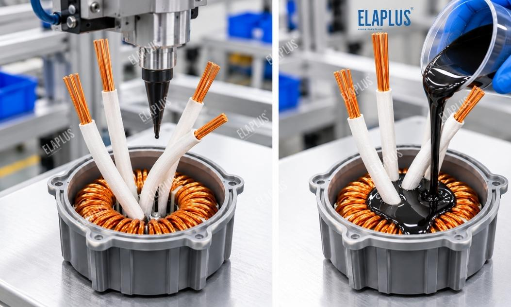
Coil Potting
Solenoid valves are widely used in industrial automation, pneumatic controls, hydraulic systems, fluid control and various electromechanical equipment. The basic principle is that energising the coil generates a magnetic field to drive the movable armature, which actuates the mechanical structure to open, close or switch the valve.
In some solenoid designs, the coil assembly is potted to protect windings, connection terminals and other fixed electrical components. A properly designed potting scheme provides insulation, moisture protection and mechanical retention. However, inappropriate potting scope, assembly positioning or thermal design can impair the performance of the electromagnetic actuator.
Therefore, material selection for solenoid potting must balance electrical protection and mechanical movement requirements. The full encapsulation approach used for static electronic modules cannot be copied indiscriminately to all solenoid configurations.
1. Why Might Potting Cause Slow Pull-In?
Reliable pull-in depends on electromagnetic force generated by the coil overcoming spring force, friction and other applied loads. Coil current, magnetic circuit geometry, armature position and operating temperature all affect final actuation.
If potting material encroaches into regions intended for free movement, mechanical resistance increases and prevents the armature from travelling through its designed stroke. For constructions where the coil chamber is fully isolated from the armature, it cannot be assumed that the potting compound contacts or obstructs the moving core.
Another root cause is deformation of the bobbin, locators or mating features during potting or curing, which alters the original mechanical clearance. For electromagnetic actuators with tight clearances, even minor dimensional shifts can disrupt kinematic fit.
Additionally, potting material modifies the thermal dissipation path of the coil. For constant-voltage driven coils, rising temperature increases copper winding resistance and reduces steady-state current. If the original electromagnetic force margin is low, pull-in performance degrades.
Note that drive topologies differ: constant-current and pulse-driven circuits do not follow the same behavioural rules as constant-voltage coils.
2. Distinguishing Mechanical vs Electrical Root Causes of Malfunction
When actuation faults appear after potting, establish a before-and-after performance baseline and verify supply conditions. For un-potted samples, record coil resistance, drive current, pull-in time and release time as reference data.
If faults consistently occur at one specific assembly orientation, focus on dimensional tolerances, fixturing and motion clearance. If failures appear randomly across units, investigate potting process, cure schedule and assembly consistency.
| Symptom | Primary Diagnostic Direction | Recommended Verification |
|---|---|---|
| Longer pull-in time after potting | Mechanical drag, coil temperature rise or drive variation | Compare actuation timing pre- and post-potting |
| No pull-in on energisation | Insufficient magnetic force or binding moving parts | Check voltage, current and travel range |
| Degraded hot pull-in capability | Winding resistance change and thermal design | Log cold/hot resistance and actuation parameters |
| Repeated faults at fixed mounting position | Bobbin distortion, positional offset or local interference | Measure critical assembly dimensions |
| Random failures across batches | Potting volume, process and assembly consistency | Compare production parameters and sample geometry |
| Abnormal release behaviour after potting | Mechanical friction, residual magnetism or release drive logic | Record release timing and motion profile |
For solenoids with standalone coil modules, validate coil electrical performance first, then test full valve assembly behaviour. If electrical parameters are acceptable on the bare coil but faults appear once mated to the valve body, inspect magnetic circuits, clearance and stack-up geometry instead of replacing potting material directly.
3. Why Should Solenoid Coils Not Be Fully Filled?
Solenoids contain both stationary electrical components and moving mechanical elements. Fixed windings, terminals and protected cavities may be potted per design intent, but the armature, valve stem and other moving parts must retain their required free clearance.
For constructions with separate coil bobbin and armature channels, define the boundary where potting material is permitted and use housings or tooling to block adhesive ingress into moving zones.
For solenoids with dedicated coil enclosures, evaluate full winding potting or local terminal potting according to the design. For mechanically located assemblies, confirm curing does not shift critical dimensions.
The goal of solenoid potting is not to maximise fill volume, but to reliably cover stationary electrical zones while preserving unimpeded mechanical operation.
4. Why PUR 1680 Is a Candidate for Coil Potting
ELAPLUS PUR 1680(D70) A/B is a two-component solvent-free polyurethane potting compound, curable at ambient temperature or with heat. It exhibits good flow after mixing and delivers a balance of hardness and toughness once cured.
It provides electrical insulation, moisture resistance and adhesion to a range of metal and plastic substrates. The datasheet specifies a mixed viscosity of 1000±500 mPa·s at 25°C, making it suitable for static electronic assemblies requiring insulation and structural filling.
For solenoid coil and terminal cavities, PUR 1680(D70) may be shortlisted. Key evaluation points include compatibility with winding insulation, coil bobbins, metal terminals and housings.
Important: this grade is specified for communications equipment, control power supplies, transformers, ignition controllers and electronic sensors. Application to solenoid valves requires structural validation and does not automatically satisfy all requirements for a given valve design.
5. How to Select Potting Materials for Solenoid Coils
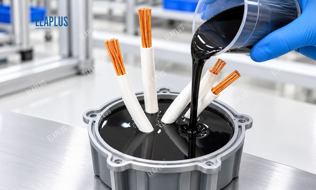
Material families differ in cured mechanical properties, processing and thermal performance. Selection should follow protection objectives; higher hardness is not inherently better.
| Material System | Main Characteristics | Suitable Constructions for Evaluation | Key Validation Items |
|---|---|---|---|
| Polyurethane potting compound | Balanced insulation, toughness and structural protection | Fixed windings, terminal protection cavities | Temperature rise, adhesion, dimensional stability |
| Silicone potting compound | Elastic after cure, suitable for temperature cycling | Stationary electrical zones requiring flexible protection | Mechanical retention, material compatibility |
| Epoxy potting compound | High rigidity and structural strength | Stationary assemblies needing robust fixation | Cure stress, bobbin deformation |
| Localised insulation potting | Minimised material volume and contact area | Terminals, lead joints and defined zones | Insulation integrity, coverage |
| No potting | Retains original geometry and thermal path | Coil modules already meeting protection requirements | Environmental reliability, insulation performance |
If the potting material is intended to participate in heat dissipation, verify its actual thermal conductivity and run full-assembly temperature-rise tests. For high-cycle or continuously energised solenoids, also consider duty cycle, coil heat generation and installation environment.
6. Controlling the Potting Process for Solenoid Coils
Before dispensing, complete electrical and dimensional checks on windings, bobbins and terminals. Use reliable barriers or masking fixtures for armature passages, mating surfaces and all no-potting regions.
During dispensing, control dispense location, fill volume and fill height according to cavity geometry to prevent adhesive intrusion into motion paths or interference with downstream assembly.
For two-component polyurethane, strictly follow the specified mix ratio, mixing method and cure profile. Process parameters from other polyurethane grades cannot be reused for PUR 1680(D70).
After potting, inspect cure state, bobbin dimensions and terminal alignment, and confirm the coil subassembly assembles correctly into the valve body.
7. Validating Actuation Reliability after Potting
Build test coupons using the actual BOM: coils, bobbins, terminals, valve bodies and drive circuits, following the planned mass-production process.
First, compare coil resistance, insulation resistance and critical assembly dimensions before and after potting to confirm the process does not alter electrical or mechanical geometry.
Next, test pull-in time, release time and actuation stability under specified supply conditions. For products with wide operating voltage ranges, verify performance across the design voltage envelope.
Temperature-rise testing is performed under rated load, duty cycle and mounting conditions. Combine hot and cold testing to assess how coil heating affects magnetic force and timing.
Environmental reliability testing includes thermal cycling, damp heat and vibration as required. Recheck insulation, dimensions and actuation performance after exposure.
ELAPLUS: Select adhesives based on service conditions, not just stack parameters. Solenoid coil potting must meet all targets for electrical protection, mechanical clearance, temperature rise and actuation reliability.
8. Potting Scheme Selection for Different Solenoid Applications
For industrial pneumatic solenoids, evaluate local potting based on coil housing and terminal layout. Confirm the material does not interfere with spool movement or final assembly.
For hydraulic control solenoids, also consider operating temperature, vibration and fluid exposure. If the potting material may contact hydraulic media, run separate chemical compatibility testing; moisture resistance alone is insufficient.
For continuously energised electromagnetic actuators, focus on coil temperature rise and hot pull-in capability. For high-frequency switching equipment, prioritise repeatability and long-term mechanical reliability.
FAQ
Q: Is slow pull-in after potting always caused by the adhesive?
A: Not necessarily. Check drive circuitry, coil temperature rise, armature clearance and assembly geometry together.
Q: Can PUR 1680 be used for solenoid coil potting?
A: It may be evaluated as a candidate for fixed coil and terminal protection zones, subject to validation on actual assemblies.
Q: Can adhesive be potted directly around the solenoid armature?
A: Moving zones should not be potted. Maintain the required clearance per structural design.
Q: Does polyurethane potting improve coil heat dissipation?
A: This depends on thermal conductivity and thermal path; conclusions cannot be drawn from the material family alone.
Q: Must pull-in timing be re-tested after potting?
A: Yes. Reconfirm actuation performance under specified supply, temperature and load conditions.