Cracking of automotive inductor potting compounds seldom stems from one single cause. It arises from combined effects of material hardness, coefficient of thermal expansion (CTE), potting thickness, cure shrinkage, heat generation from coils and repeated thermal cycling. For inductors requiring low‑stress thermal conduction, ELAPLUS SIPA 1850‑series thermally‑conductive silicones are prime candidates. For magnetic components demanding enhanced structural support, suitable epoxy systems shall be further evaluated.
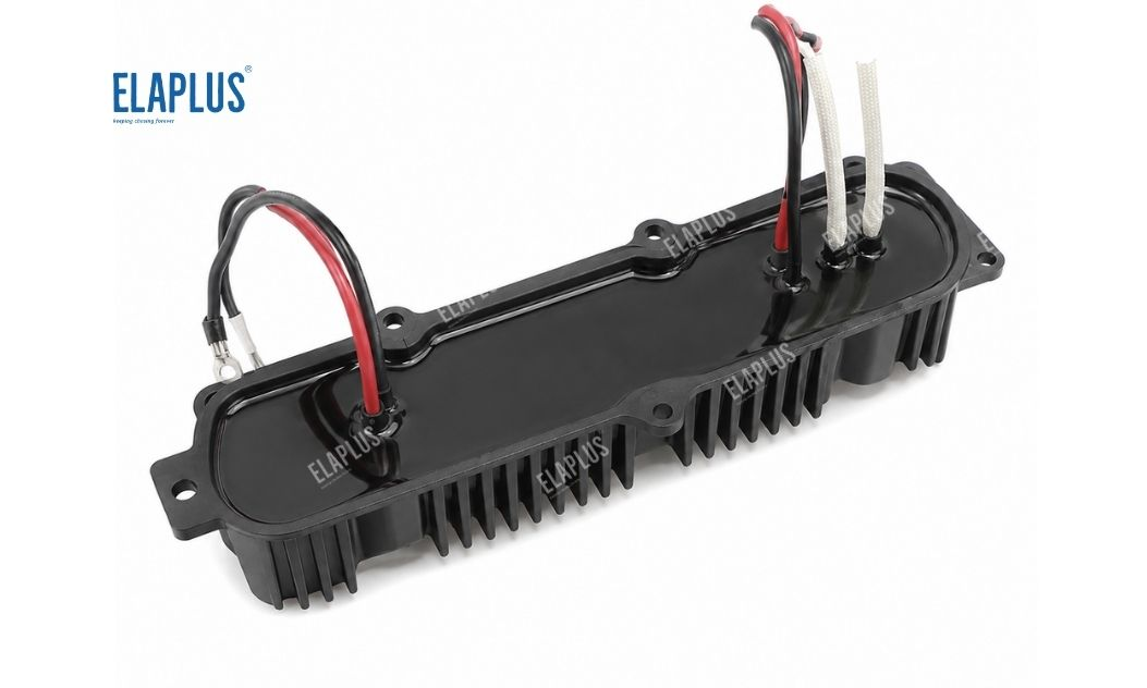
Inductor potting
Why Are Inductors Prone to Potting Cracks?
An inductor assembly comprises copper windings, magnetic cores, bobbins, PCBs, metal housings and potting resin.
All these components feature mismatched CTE values. During operation, copper windings generate heat; each material expands to varying degrees upon heating and contracts while cooling. This creates cyclic deformation: expansion → contraction → expansion → contraction.
When a high‑hardness potting material is applied, mechanical stress tends to concentrate at:
‑ Magnetic core edges
‑ Housing corner sections
‑ Coating‑to‑coil interfaces
‑ Thick resin cross‑sections
Cracks may eventually initiate at these stress‑concentration zones.
Why Thermal Conductivity Should Not Be the Sole Selection Metric for Inductor Potting Compounds
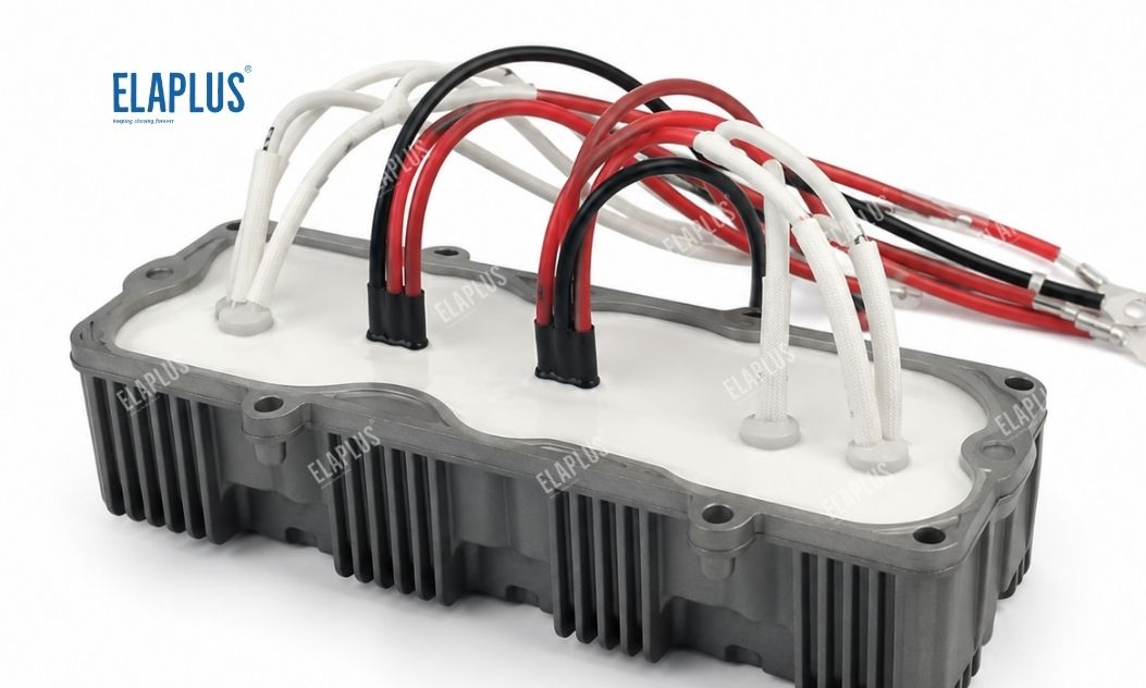
High thermal conductivity is achieved by loading substantial thermally‑conductive fillers. Increased filler content generally exerts side‑effects on:
‑ Viscosity
‑ Density
‑ Flow property
‑ Post‑cure mechanical performance
Even when thermal conductivity is raised from 1.5 W/m·K up to 3 W/m·K or higher, it is critical to verify whether the resin can fully penetrate fine coil gaps. Trapped voids inside windings will render high intrinsic thermal conductivity ineffective.
Why SIPA 1850 Is Suitable for Low‑Stress Inductor Potting
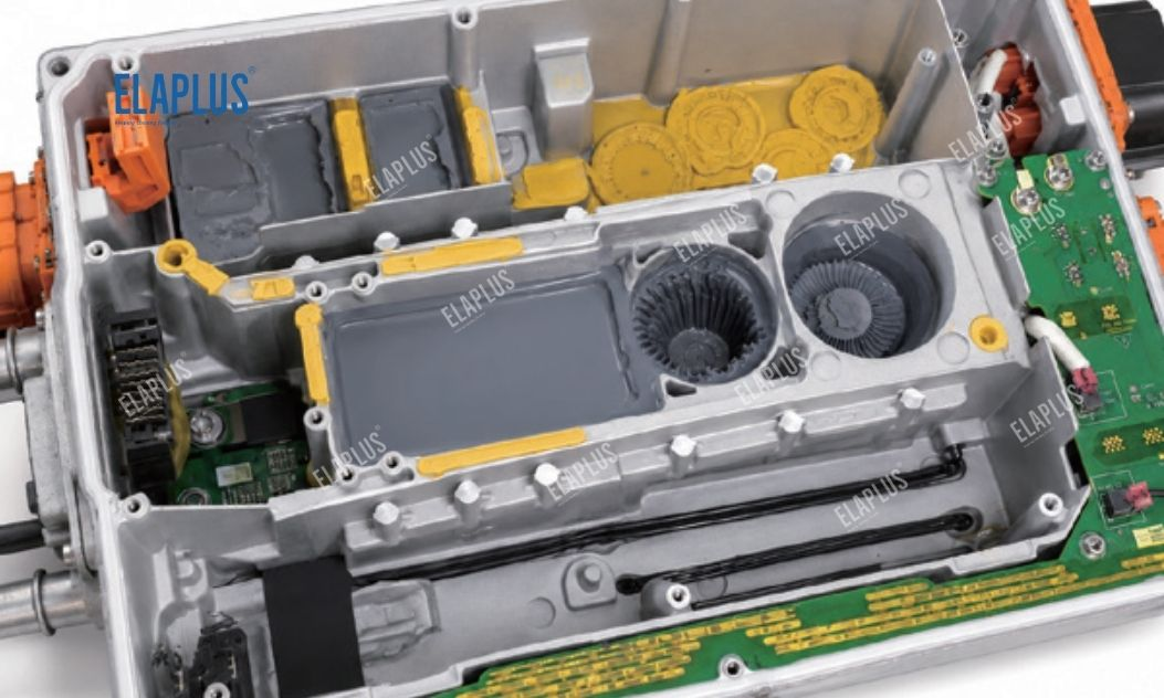
OBC inductor potting
SIPA 1850 is a thermally‑conductive silicone potting system. It serves applications including: OBC inductors 、Motor control units 、Power supply modules 、Energy‑storage inductors 、High‑power magnetic components
Multiple thermal‑conductivity grades are available for different thermal‑design targets. Cured silicone retains elastomeric properties, making it well‑suited for magnetic components exposed to severe thermal cycling.
Why Vacuum Degassing Is Required for Inductor Potting
Numerous micro‑gaps exist within inductor windings. Air must escape from coil clearances and bottom cavities while resin is poured from the top. Air entrapment occurs under the following conditions:
‑ Excessively fast dispensing speed
‑ Excessive material viscosity
‑ Densely packed coil windings
‑ Improper vacuum‑processing parameters
For large‑size inductors, a combined process workflow is recommended: pre‑heating → vacuum treatment → slow potting → secondary degassing. Exact process parameters shall be adjusted according to specific hardware geometry.
Troubleshooting Guide for Cracked Inductor Potting
Carry out diagnosis step‑by‑step:
- Crack location Housing edges? Around magnetic cores? On coil surfaces? Or full‑thickness through‑cracks?
- Crack timing Cracks appearing immediately after cure: focus on cure shrinkage and dispensing processes. Cracks occurring after thermal cycling: focus on CTE and material modulus.
- Potting layer thickness Large‑volume encapsulation builds up more complex internal stress.
- Local hot‑spot risk Local overheating creates amplified temperature gradients.
FAQ for Inductor Potting Compound Selection
Does softer potting material always deliver better crack resistance?
Flexible materials help buffer thermal‑mechanical stress. Nevertheless, structural anchoring and thermal‑conductive performance must also be taken into consideration.
What causes heavy bubble formation during inductor potting?
Difficult‑to‑vent air trapped inside dense coil windings represents one major root cause.
Is vacuum equipment mandatory for high‑thermal‑conductivity potting?
The requirement depends on material viscosity, component geometry and void‑acceptance criteria. Vacuum processes are strongly recommended for tightly‑wound high‑density coils.
ELAPLUS | Original Manufacturer | Application‑engineering Support | Free Sample Requests 📧 info@elaplus.cc
Previous post: How to Select Potting Compounds for New‑Energy‑Vehicle ECUs? How to Balance Waterproofing, Vibration Resistance and Thermal Conductivity?
Next post: How to Select Insulating Adhesives for 800V High‑Voltage Systems? Adhesive Guide for Three‑Phase Copper Busbars, Terminals and High‑Voltage Accessories