Material selection for new‑energy‑vehicle ECUs shall first determine whether full potting, partial potting, thermal gap filling or conformal coating is required based on ECU mechanical construction. For controllers requiring low‑stress full‑module protection, Elaplus SIPA 1850 thermally‑conductive silicone potting system may be evaluated. PUR‑series formulations are an option for structures demanding flexible protection. For gap‑type heat dissipation between ECU power devices and housings, TCMP 1935 thermal conductive gels can be deployed.
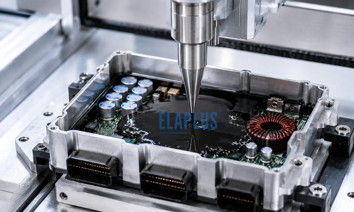
ECU Potting for Automotive Electronics
Why “Fully‑filled Potting” Does Not Equal Reliable ECU Protection
An ECU typically integrates multiple components:
‑ MCU chips
‑ MOS power devices
‑ PCBs ‑ Capacitors
‑ Electrical connectors
‑ Copper busbars
‑ Aluminum housings
Different zones face distinct failure risks.
For instance, PCBs mainly require moisture‑proofing and vibration resistance; MOSFETs call for effective heat dissipation; connector root sections need waterproof protection; housings rely on reliable sealing.
Accordingly, a single ECU may adopt a combined material solution: potting compounds + thermal conductive gels + sealants + conformal coatings, rather than depending on one single adhesive to cover all requirements.
Why Low‑stress Formulations Are Preferred for Full ECU Potting
Numerous solder joints are populated on PCBs. When high‑hardness resin is applied for large‑volume encapsulation, stress generated by cure shrinkage and thermal cycling can transfer onto:
‑ BGA packages
‑ Solder joints
‑ Capacitors
‑ Semiconductor chips
‑ Connector root terminals
Low‑stress performance therefore becomes a critical selection criterion for assemblies populated with stress‑sensitive electronics.
Elaplus SIPA 1850 Two‑Component Thermally‑Conductive Silicone Potting Compound
Recommended for applications where both thermal performance and low‑stress encapsulation are required.
Thermal‑dissipation Solutions for ECU Power Devices
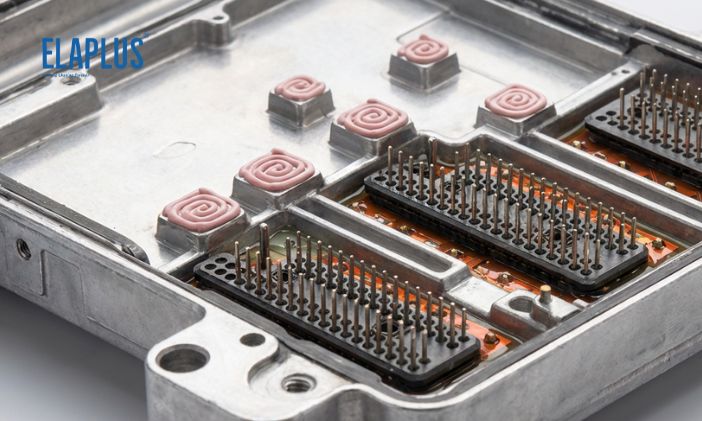
If heat bottlenecks occur exclusively at the interface between MOSFETs and metal housings, massive full‑volume potting is unnecessary to resolve a localized thermal issue.
Instead, TCMP 1935 two‑component liquid thermal conductive gel fills gaps between power components and heat‑dissipation housings, establishing a thermal‑transfer path: MOSFET → TCMP gel → aluminum housing.
Is Potting Compound Alone Sufficient for ECU Waterproof Performance?
No. Water can infiltrate through multiple pathways:
‑ Housing joint gaps
‑ Connectors
‑ Connector pin terminals
‑ Wire harness exit points
Long‑term ECU waterproof capability depends on a complete system‑level sealing design. Connector pin terminals in particular represent frequently‑overlooked micro‑leakage paths.
Full Potting vs Conformal Coating for ECU Design
Full Potting
Best suited for:
‑ Harsh operating environments
‑ High anti
‑vibration requirements
‑ Elevated IP waterproof‑rating targets
‑ Combined thermal‑dissipation demands
Conformal Coating
Best suited for:
‑ Weight‑reduction targets
‑ Repairable PCBA assemblies
‑ No large‑scale structural anchorage requirements
‑ Primary protection against moisture and chemical corrosion
These two technologies are not simple substitutes for one another.
FAQ for ECU Adhesive & Potting Selection
Is softer potting compound always better for ECU applications?
No. Mechanical support, vibration damping and structural fixation requirements must also be considered.
What causes delamination between potting resin and aluminum ECU housings?
Root causes may include surface oil contamination, aluminum oxide layers, insufficient surface pre‑treatment, potting‑material internal stress and substrate‑material incompatibility.
Can high‑performance thermal grease be used for full ECU potting?
Thermal interface grease cannot be used as a structural potting material; they serve fundamentally different functional purposes.
Free‑of‑charge Sample Request & Technical Selection Support: info@elaplus.cc