The core performance metric for thermal‑interface materials of IGBT and SiC power modules is not standalone thermal‑conductivity value, but the actual interfacial thermal resistance. Real‑world heat‑dissipation performance is governed by thermal conductivity, bond‑line thickness (BLT), contact area, compression ratio, interfacial wet‑out property and long‑term pump‑out stability. For new‑energy‑vehicle inverters, MCUs and high‑power power supplies, Elaplus TIM grades such as TCMP 1935 and TCMP 3380 may be evaluated.
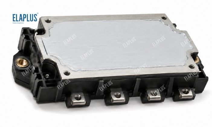
Why SiC Devices Place Higher Demands on Thermal‑interface Materials
One major advantage of SiC semiconductors lies in higher switching frequency and elevated power density.
Meanwhile, system hardware becomes more compact. This leads to the following chain effect: Same footprint → higher power load → increased heat‑flux density per unit area → thermal interface performance becomes more critical. Poor TIM interface control will trigger rapid chip‑junction‑temperature rise.
What Is Interfacial Thermal Resistance?
Heat flows from semiconductor chips toward heat sinks via intermediate thermal‑interface materials. Thermal resistance is not determined solely by material thermal conductivity.
Simple illustration:
‑ Material A: 8 W/m·K, bond‑line thickness 1.5 mm
‑ Material B: 5 W/m·K, bond‑line thickness 0.3 mm
We cannot judge which one delivers lower thermal resistance merely by comparing 8 vs 5. Thicker bond‑line means longer heat‑transfer path. Well‑designed TIM selection must consider thermal conductivity together with bond‑line thickness (BLT).
Why Thermal Conductive Gels Are Suitable for IGBT & SiC Power Modules
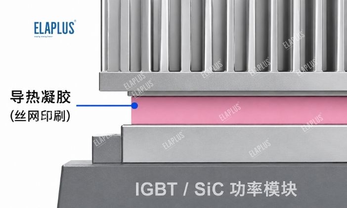
Mismatches frequently occur between power modules and housing assemblies, including:
‑ Manufacturing tolerances
‑ PCB warpage
‑ Component height offset
‑ Heat‑sink flatness deviation
Thermal conductive gels deform mechanically to fill these micro‑gaps.
Elaplus TCMP 1935 Two‑Component Liquid Gap Filler
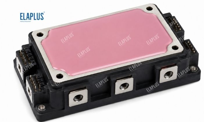
It builds stable thermal interfaces for IGBT, SiC, MCU, ECU and general power‑electronic modules.
Why Reworkability Gains Growing Importance
During prototype development of new‑energy‑vehicle electronic assemblies, engineers repeatedly perform:
Disassembly → failure analysis → re‑assembly → re‑validation testing.
Non‑reworkable TIMs significantly raise R&D and field‑repair costs. Accordingly, compressible, rework‑oriented materials such as TCMP 3380 offer distinct advantages for certain mechanical designs.
Key Questions for TIM Material Evaluation
Do not only ask: What is its thermal conductivity?
You should also verify the following parameters:
‑ What is the actual assembly gap?
‑ What is the minimum achievable BLT?
‑ What is the maximum allowable compression ratio?
‑ What mechanical pressure can components withstand?
‑ Is reworkability required?
‑ Does the material support automated dispensing?
‑ Is vertical sagging / flow‑out a concern?
‑ Does pump‑out occur after long‑term high‑temperature exposure?
‑ Does interfacial performance remain stable through thermal cycling?
‑ What is the measured real‑world thermal resistance?
FAQ for TIM Selection of IGBT & SiC Power Modules
Do SiC devices always require TIMs with higher thermal conductivity than IGBT applications?
No simple yes‑or‑no answer. Selection shall be determined comprehensively by device heat‑flux density, cooling architecture and bond‑line thickness.
Do entrapped bubbles inside TIM affect performance?
Yes. Air voids increase localized interfacial thermal resistance. Bubble suppression shall be controlled throughout dispensing and compression‑mounting processes.
Are thermal conductive gels identical to thermally‑conductive potting compounds?
They serve different purposes. Thermal conductive gels focus on interfacial gap filling; potting compounds deliver large‑area electronic encapsulation together with thermal conduction.
ELAPLUS | Thermal‑interface‑material Application Support 📧 info@elaplus.cc

Previous post: What Thermal Materials for Automotive Motor Controller (MCU)? How to Select Between Thermal Conductive Gel, Thermal Grease and Thermal Pads
Next post: How to Select Potting Compounds for New‑Energy‑Vehicle ECUs? How to Balance Waterproofing, Vibration Resistance and Thermal Conductivity?